Level Switch 3d Cad
Level Switch 3d Cad
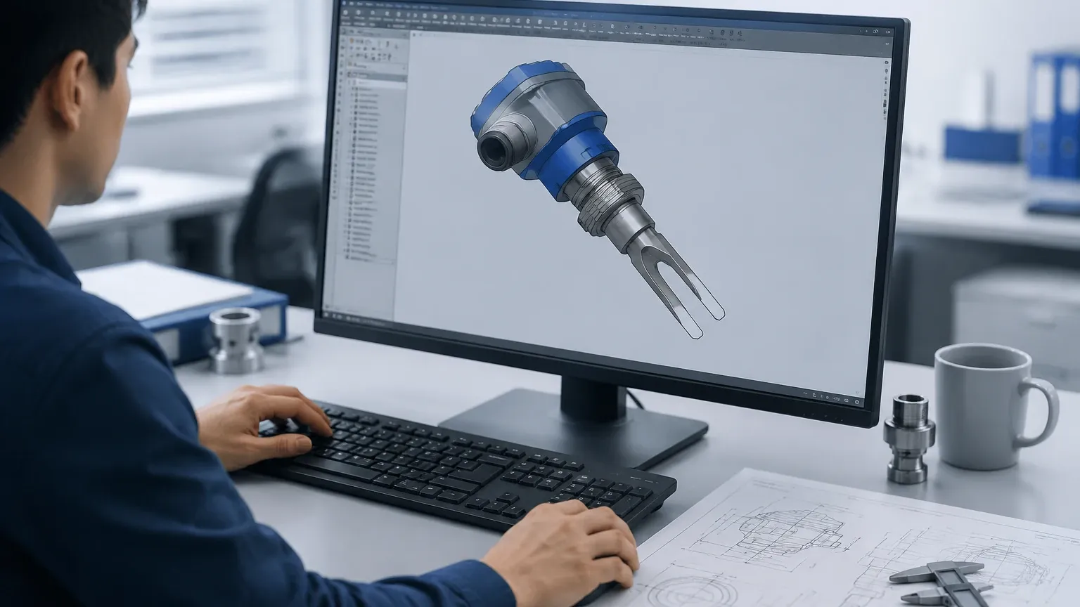
In modern industrial plant design, the integration of instrumentation into complex piping and vessel layouts requires high precision. The use of a level switch 3d cad model has become a standard requirement for mechanical and process engineers to ensure that hardware fits within the physical constraints of a system. Beyond simple spatial fit, these models allow for the simulation of mounting orientations, cable tray routing, and maintenance access clearances before a single component is purchased or installed.
Level switches are critical components in automation, serving as point-level detection devices that prevent tank overflows, protect pumps from dry running, or signal the need for a refill. This article explores the technical principles of these instruments, the necessity of accurate 3D modeling in the design phase, and the practical considerations for selecting and installing the right technology.
Core Measurement Principles of Level Switches
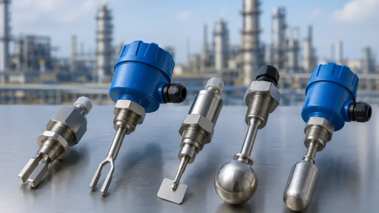
Before integrating a Level Switches model into a digital twin or plant layout, it is essential to understand the underlying technology. Different measurement principles dictate the physical form factor and the necessary clearances required in the 3D environment.
Vibrating Tuning Fork Switches
These switches utilize a piezoelectric crystal to vibrate a metal fork at its natural resonant frequency in the air. When the fork is submerged in a liquid or solid, the frequency shifts or the vibration is dampened. An electronic circuit detects this change and triggers a relay or transistor output. Because the fork must be free to vibrate, the level switch 3d cad must account for the "swing diameter" and ensure no internal tank structures interfere with the tines.
Float and Magnetic Level Switches
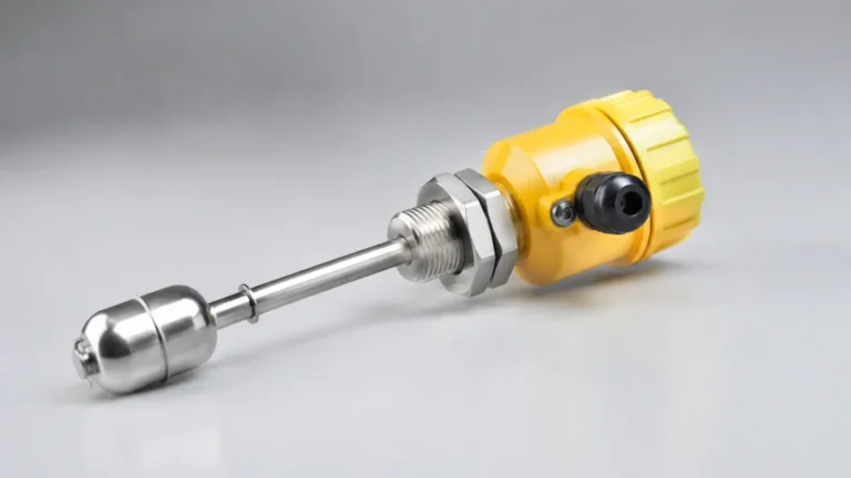
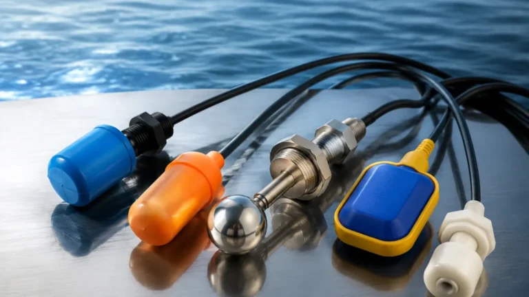
Float-based switches operate on the principle of buoyancy. A float containing a magnet moves along a stem as the liquid level rises or falls. When the magnet reaches a specific point, it actuates a reed switch located inside the stem. In 3D modeling, engineers must account for the travel distance of the float and ensure that the "dead zone" at the top and bottom of the stem is factored into the switching point logic.
Capacitive Level Switches
Capacitance switches measure the change in electrical capacitance between the sensor electrode and the tank wall (or a reference electrode). As the medium covers the probe, the dielectric constant changes, signaling the presence of the material. These are often used for both liquids and solids. The CAD model for these units is typically a solid probe, but the engineer must consider the "active zone" of the probe relative to the vessel wall.
Rotary Paddle Switches
Commonly used for bulk solids, a small electric motor slowly rotates a paddle. When the material reaches the paddle, it creates torque that trips a microswitch and stops the motor. The 3D model for a rotary switch is particularly important because the paddle's rotation radius must be completely clear of any internal baffles or structural supports within the silo.
The Importance of Level Switch 3D CAD in System Design
The transition from 2D drafting to 3D modeling has significantly reduced field errors. Utilizing a level switch 3d cad file during the FEED (Front-End Engineering Design) phase provides several technical advantages:
1. Interference Detection: Automated clash detection software can identify if a level switch probe will hit an internal agitator, heating coil, or baffle. This is especially critical for long-reach probes used in large tanks.
2. Nozzle Alignment: Engineers can verify that the mounting nozzle on the vessel is at the correct height and orientation. If a switch is mounted too close to an inlet pipe, turbulence might cause false triggering; a 3D model helps visualize these fluid dynamics.
3. Maintenance Access: A 3D model allows designers to simulate the space required for a technician to unscrew the housing cover, attach conduit, or remove the entire unit for calibration without hitting overhead pipes or walkways.
4. Orientation Accuracy: For horizontal mounting, the orientation of the cable entry is vital to prevent moisture ingress. 3D models allow for the precise rotation of the housing in the design software to ensure the cable gland points downward.
Selection Criteria for Industrial Level Switches
Choosing the correct switch involves more than just matching a thread size. The process conditions dictate the material of construction and the sensing technology. The following table provides a general guideline for technology selection based on common industrial parameters.
| Technology | Suitable Media | Max Temperature | Max Pressure | Primary Advantage |
| :— | :— | :— | :— | :— |
| Vibrating Fork | Liquids / Fine Powders | Up to 150°C | Up to 64 bar | High reliability, no calibration |
| Float Switch | Clean Liquids | Up to 120°C | Up to 40 bar | Simple, low cost, no power needed |
| Capacitive | Liquids / Slurries / Solids | Up to 200°C | Up to 100 bar | Handles coating/buildup well |
| Rotary Paddle | Bulk Solids / Grains | Up to 80°C | Atmospheric | Robust for heavy materials |
| Ultrasonic Gap | Non-foaming Liquids | Up to 130°C | Up to 100 bar | No moving parts, very accurate |
When evaluating a level switch 3d cad for a specific project, ensure the model reflects the exact process connection (e.g., G1/2", 1.5" NPT, or DN50 Flange) to avoid mismatches during the assembly phase.
Technical Specifications and CAD Data Requirements
A high-quality 3D model for an industrial level switch should include more than just the exterior shell. For precise engineering, the following data points should be confirmed within the CAD file or the accompanying datasheet:
* Insertion Length (L): The distance from the process connection sealing surface to the tip of the sensor. In many cases, this is a customizable variable.
* Housing Dimensions: The width and height of the electronics enclosure, including the space required for the cable glands.
* Wetted Materials: While not always visible in a CAD model, the metadata should specify if the probe is 316L Stainless Steel, PTFE-coated, or Hastelloy.
* Switching Point: The exact vertical coordinate where the switch is expected to actuate. For float switches, this is usually the center of the float; for tuning forks, it is typically near the base of the tines.
Installation Considerations and Physical Constraints
Correct installation is as important as correct selection. Even with a perfect level switch 3d cad integration, field conditions can lead to failure if basic engineering principles are ignored.
Mounting Position
* Top Mounting: Preferred for float and ultrasonic gap switches. Ensure the probe length is calculated from the top of the nozzle, not the top of the tank.
* Side Mounting: Common for tuning forks and rotary paddles. The switch should be angled slightly downward (approx. 20 degrees) in solids applications to prevent material from accumulating on the sensor base.
Turbulence and Agitation
If the tank contains an agitator, the level switch must be placed in a "quiet zone." If this is not possible, a stilling well (a bypass pipe) may be required. The 3D CAD model must include this stilling well to check for clearances against the agitator blades.
Nozzle Length
For vibrating fork switches, the tines must extend fully into the vessel. If the mounting nozzle is too long, the tines will be trapped inside the nozzle neck, where material can build up and cause a "deadlock" or false signal. The CAD model should verify that the active sensing element is at least 10mm to 20mm past the inner wall of the tank.
Limitations of Digital Modeling
While a level switch 3d cad provides excellent spatial data, it cannot simulate all environmental factors. Engineers must manually account for the following:
* Dielectric Constant (εr): For capacitive switches, the CAD model will not tell you if the media has a high enough dielectric constant to be detected. This requires a review of the material safety data sheet (MSDS).
* Chemical Compatibility: The 3D model shows the shape of the 316SS probe, but it does not warn you if the process fluid (e.g., Hydrochloric Acid) will corrode that material. Always cross-reference the wetted parts with a chemical resistance chart.
* Electrical Noise: 3D models do not show electromagnetic interference (EMI). Ensure that signal cables are shielded and kept away from high-voltage motor leads, regardless of how clean the cable routing looks in the CAD software.
Frequently Asked Questions (FAQ)
Q: What file formats are most common for level switch 3D models?
A: Most manufacturers provide files in STEP (.stp or .step), IGES (.igs), or Parasolid (.x_t) formats. These are neutral formats that can be opened by SolidWorks, AutoCAD, Rhino, and Siemens NX.
Q: Can I use a 2D drawing instead of a 3D CAD model?
A: While 2D drawings provide dimensions, they are prone to interpretation errors regarding orientation and clearances. 3D models are highly recommended for complex assemblies to perform automated clash detection.
Q: Does the CAD model include the internal wiring?
A: Generally, no. Industrial 3D models represent the physical envelope and process connections. Internal wiring and circuit board layouts are proprietary and are not included in the customer-facing CAD files.
Q: How do I account for the "dead zone" in my 3D design?
A: The dead zone is the area where the switch cannot detect level (e.g., the very top of a float stem). You should refer to the manufacturer's datasheet and mark these zones in your 3D assembly as "keep-out" areas to ensure the process logic accounts for the physical limits of the sensor.
By integrating a detailed level switch 3d cad into the project workflow, engineering teams can ensure a seamless transition from the design office to the plant floor. This proactive approach minimizes costly field modifications and ensures that the Level Switches function reliably within their intended environment.