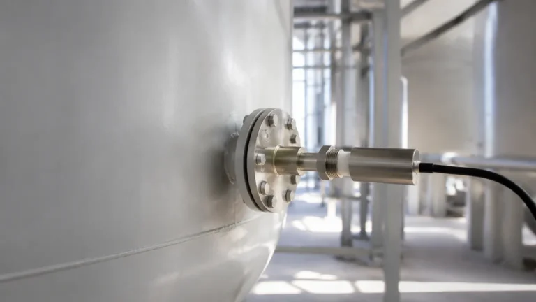
Level Switch Gestra
Level Switch Gestra
In the demanding environment of industrial steam generation and thermal oil systems, level control is not merely a matter of process efficiency but a critical safety requirement. The term "level switch gestra" refers to a specialized category of high-integrity level detection instruments designed primarily for boilers and high-pressure vessels. These systems are engineered to prevent catastrophic failures, such as boiler dry-firing or water carry-over into steam turbines, by providing reliable high-level and low-level alarms.
Understanding the technical nuances of these switches is essential for plant engineers and maintenance professionals. This guide explores the measurement principles, selection criteria, and installation best practices for high-pressure Level Switches, ensuring operational safety and regulatory compliance.
Measurement Principles of Boiler-Grade Level Switches
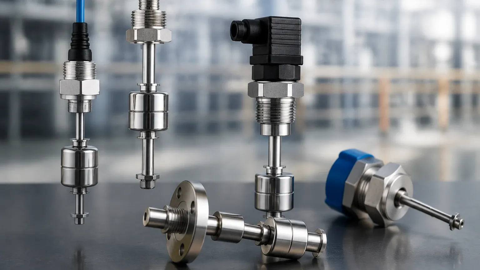
Level switches used in steam and condensate applications typically rely on two primary physical principles: conductivity and capacitance. Unlike float-based systems that may suffer from mechanical fatigue or sticking in high-pressure environments, these electronic methods offer no moving parts within the process vessel.
1. The Conductivity Principle
Conductivity level switches are the industry standard for water-based steam boilers. This principle relies on the fact that water (especially boiler water with dissolved solids) conducts electricity, while steam acts as an insulator.
* Operation: An electrode is inserted into the vessel. A low-voltage, high-frequency AC current is applied to the electrode. When the water level rises and touches the electrode tip, the circuit is completed through the liquid to the vessel wall (or a reference electrode). This change in current is detected by a controller, which then triggers a relay.
* Self-Monitoring: High-integrity systems, often associated with the level switch gestra range, feature self-monitoring electrodes. These units can detect insulation breakdowns or cable breaks, ensuring that a component failure results in a "fail-safe" alarm state. This is critical for meeting SIL (Safety Integrity Level) requirements.
2. The Capacitance Principle
Capacitance switches are used when the medium is non-conductive (such as thermal oil) or when continuous level monitoring is required alongside point switching.
* Operation: The electrode and the vessel wall form the two plates of a capacitor. As the liquid level rises, it displaces the air or steam (which has a low dielectric constant) with the process medium (which has a higher dielectric constant). This change in capacitance is proportional to the level and is converted into a switching signal or a continuous 4-20mA output.
Key Evaluation Criteria for Selection
Selecting a level switch for high-pressure or high-temperature service requires a rigorous assessment of the application's physical and chemical parameters. The following table provides a comparison of typical specifications for industrial level switches.
Selection Comparison Table
| Feature | Conductivity Switches | Capacitance Switches | Magnetic Float Switches |
| :— | :— | :— | :— |
| Primary Media | Conductive liquids (Water) | Conductive & Non-conductive | Most clean liquids |
| Max Pressure | Up to 160 bar (2320 psi) | Up to 100 bar (1450 psi) | Up to 40 bar (580 psi) |
| Max Temperature | Up to 350°C | Up to 400°C | Up to 250°C |
| Maintenance | Low (No moving parts) | Low | Moderate (Moving parts) |
| Safety Integrity | SIL 2 / SIL 3 capable | SIL 2 capable | Generally SIL 1 |
| Sensitivity | Adjustable for low conductivity | High sensitivity required | Density dependent |
Pressure and Temperature Ratings
In steam applications, the relationship between pressure and temperature is fixed. For example, saturated steam at 32 bar has a temperature of approximately 238°C. A level switch gestra-type assembly must be rated for both the maximum operating pressure and the corresponding saturation temperature, with a safety margin for transient surges.
Media Conductivity
For conductivity switches, the minimum conductivity of the water (measured in µS/cm) is vital. Standard boiler water usually has sufficient conductivity, but ultra-pure condensate or deionized water may require high-sensitivity controllers to ensure reliable switching.
Installation and Commissioning Considerations
Proper installation is the most significant factor in the long-term reliability of a level switch. Errors during mounting can lead to false alarms or, more dangerously, a failure to trip during a low-water event.
1. Electrode Trimming
Many conductivity electrodes are supplied as long rods that must be cut to the specific "switch point" length on-site.
* Measurement: Always measure from the sealing surface of the flange or thread, accounting for the thickness of the gasket.
* Insulation: Ensure that the insulation sleeve remains intact after cutting. If the bare metal of the electrode touches the vessel wall or a protection tube, a permanent "high level" signal will be generated.
2. Protection Tubes (Stilling Wells)
In boilers where internal turbulence or foaming is common, electrodes should be installed inside a protection tube (stilling well). This tube acts as a mechanical buffer, ensuring the water level around the electrode is stable. The tube must have vent holes at the top and bottom to allow for pressure equalization and fluid flow.
3. Wiring and Interference
Because the signals generated by conductivity and capacitance probes are often low-voltage, they are susceptible to electromagnetic interference (EMI).
* Use shielded cabling for all connections between the probe and the controller.
* Route level switch cables away from high-power motor leads or frequency inverters.
* Ensure a dedicated, high-quality ground connection to the vessel wall.
Common Risks and Limitations
While industrial Level Switches are robust, they are not immune to environmental challenges. Understanding these risks allows for better preventative maintenance.
* Scaling and Deposits: In hard water applications, calcium or silica scale can build up on the electrode. While conductivity switches are somewhat resistant, heavy scaling can insulate the probe, preventing it from detecting the water. Regular visual inspections during boiler blowdown are recommended.
* Foaming: High concentrations of dissolved solids or chemical imbalances can cause foaming in the boiler. A conductivity probe may detect the foam as liquid, leading to a false high-level reading. Proper water treatment and surface blowdown are the primary defenses against this issue.
* Insulation Breakdown: Over years of service, the ceramic or PTFE insulation at the electrode head may degrade due to thermal cycling. Self-monitoring controllers are designed to detect this, but manual testing of the alarm circuit should be performed weekly in accordance with local boiler regulations (such as EN 12952-7 or ASME BPVC).
Maintenance and Functional Safety Testing
For systems providing "Low Water" protection, periodic functional testing is mandatory. This usually involves a "low-water test," where the boiler water level is intentionally lowered under controlled conditions to verify that the burner shuts down and the alarm activates.
1. Daily/Weekly Tests: Use the test button on the controller to simulate an electrode fault.
2. Annual Inspection: Remove the electrodes to check for corrosion, scaling, or mechanical damage. Check the resistance of the insulation; a reading below a certain threshold (typically 2 MΩ) indicates that the probe should be replaced.
3. Controller Calibration: For capacitance-based systems, recalibrate the zero and span points if the process medium characteristics have changed significantly.
Frequently Asked Questions (FAQs)
Q: Can a level switch gestra be used in hazardous areas?
A: Yes, many models are available with ATEX or IECEx certifications for use in explosive atmospheres. These typically require the use of intrinsic safety (IS) barriers between the probe and the control room.
Q: What is the difference between a 1-pole and a 4-pole electrode?
A: A 1-pole electrode provides a single switching point (e.g., Low Water). A 4-pole electrode contains four separate rods of different lengths within a single housing, allowing for High Alarm, Pump On, Pump Off, and Low Alarm in one installation point.
Q: Why does my level switch trigger when the pump starts?
A: This is likely due to turbulence or the "swell" effect in the boiler. When steam demand increases or a pump starts, the pressure drop causes steam bubbles to expand, momentarily raising the water level. Increasing the damping (delay) time on the controller or installing a stilling well can resolve this.
Q: Is it possible to use these switches for oil-water separation?
A: Capacitance switches are excellent for this, as they can distinguish between the dielectric constants of oil (~2.0) and water (~80). Conductivity switches will only detect the water phase.
Conclusion
High-integrity level switches are the silent guardians of industrial thermal processes. Whether utilizing the conductivity principle for steam boilers or capacitance for thermal oils, the reliability of a level switch gestra-type system depends on precise selection and meticulous installation. By adhering to established engineering standards and performing regular maintenance, operators can ensure that their level measurement systems provide accurate, fail-safe protection for years to come. For those seeking versatile solutions for diverse industrial media, exploring a wide range of Level Switches is the first step toward optimizing plant safety and efficiency.