How to Level Switches
How to Level Switches
In industrial process control, point level detection serves as a critical safeguard for equipment protection, inventory management, and operational safety. Understanding how to level switches—referring to the selection, installation, and calibration of these devices—is essential for any engineering team tasked with managing liquid or solid storage systems. Unlike continuous level transmitters that provide a constant data stream (e.g., 4-20mA or HART), level switches provide a discrete output when a specific threshold is reached. This guide explores the engineering principles, selection logic, and practical implementation of these vital components.
Measurement Principles of Level Switches
Before determining how to level switches for a specific application, it is necessary to understand the underlying physics of the various technologies available. Each principle offers distinct advantages depending on the physical properties of the media.
Float Level Switches
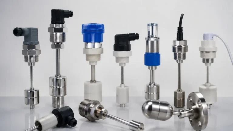
Float switches operate on the principle of buoyancy. A float containing a magnet moves with the liquid level. When the float reaches a predetermined point, the magnetic field actuates a reed switch or a microswitch. These are among the most common and cost-effective solutions for clean liquids. They are purely mechanical in their primary sensing action, requiring no external power for the sensing element itself in many configurations.
Vibrating (Tuning Fork) Level Switches
Vibrating switches utilize a tuning fork-shaped sensing element excited by a piezoelectric crystal at its natural resonant frequency. When the fork is immersed in a medium (liquid or solid), the frequency of vibration changes or the vibration is damped entirely. An electronic circuit detects this shift and triggers the switch output. This technology is highly reliable because it is largely independent of the medium's chemical properties, such as conductivity or dielectric constant.
Capacitance Level Switches
Capacitance switches treat the sensor probe and the tank wall (or a reference ground) as two plates of a capacitor. The medium between them acts as the dielectric. As the level rises and covers the probe, the dielectric constant changes, leading to a change in capacitance. This change is measured and converted into a switching signal. These are excellent for detecting interfaces or working with corrosive materials, provided the dielectric constant is stable.
Rotary Paddle Level Switches
Designed specifically for bulk solids and powders, rotary paddle switches use a low-speed motor that rotates a paddle. When the material reaches the paddle, it creates mechanical resistance, causing the motor to stall or shift. This mechanical movement triggers a microswitch. They are robust and ideal for silos containing grains, plastic pellets, or ores.
Hydrostatic and Pressure Switches
While often used for continuous measurement, pressure-based switches trigger when the head pressure of a liquid column exceeds a set point. These are frequently used in water treatment and deep-well applications where mounting from the top of the vessel is impractical.
Selection Criteria: How to Level Switches Effectively
Choosing the right technology requires a deep dive into the process conditions. If the selection is incorrect, the switch may fail to trigger (leading to overflows) or trigger prematurely (causing unnecessary downtime).
1. Media Characteristics: Is the material a liquid, a slurry, or a bulk solid? Consider viscosity, density, and whether the material tends to coat the sensor (buildup). For coating materials, vibrating forks or specialized capacitance probes are preferred.
2. Process Environment: Temperature and pressure are the primary limiters. Standard plastic float switches may only handle up to 80°C (176°F), whereas stainless steel vibrating forks can withstand temperatures exceeding 250°C (482°F) and high-pressure environments up to 64 bar (928 PSI).
3. Chemical Compatibility: The wetted parts must be resistant to the process media. Common materials include 316L Stainless Steel, PP, PVC, and PTFE. For highly aggressive acids, specialized coatings are required.
4. Output Requirements: Does the control system require a relay (SPDT/DPDT), a transistor (PNP/NPN), or a two-wire AC/DC connection? Modern Level Switches offer versatile electronic inserts to match PLC or DCS requirements.
Practical Selection Table
| Technology | Best For | Temperature Range | Pressure Range | Limitations |
| :— | :— | :— | :— | :— |
| Float | Clean liquids, water | -20°C to 120°C | Up to 20 bar | Susceptible to scaling/debris |
| Vibrating Fork | Liquids, powders, oils | -50°C to 250°C | Up to 64 bar | High-viscosity liquids (>10,000 cP) |
| Capacitance | Corrosive media, interfaces | -40°C to 200°C | Up to 40 bar | Requires stable dielectric constant |
| Rotary Paddle | Grains, sand, pellets | -20°C to 80°C | Atmospheric | Mechanical wear over time |
| Conductivity | Conductive liquids | -20°C to 100°C | Up to 10 bar | Only for conductive media |
Installation Considerations
Proper installation is as important as selection. Even the best sensor will fail if placed in a turbulent zone or near an intake pipe. When planning how to level switches for your facility, consider the following engineering guidelines:
Orientation and Mounting
* Vertical Mounting: Usually preferred for high-level alarms to ensure the sensor is out of the way of sediment. For float switches, vertical mounting allows for the longest travel distance.
* Horizontal Mounting: Common for low-level detection or mid-tank control. Ensure the switch is angled slightly or designed to prevent liquid from pooling on the sensor head, which could cause a false trigger.
Avoiding Interference
* Turbulence: If the tank has an agitator or high-velocity inflow, use a stilling well or bypass chamber to protect the switch from mechanical stress and false readings.
* Nozzle Length: For vibrating forks and capacitance probes, ensure the active sensing element extends beyond the mounting nozzle and into the vessel. If the probe is recessed within a nozzle, material may become trapped, leading to a "stuck" signal.
* Proximity to Walls: Capacitance switches require a specific distance from the tank wall to avoid interference with the electromagnetic field. Consult the manufacturer's manual for minimum clearance distances (usually 50mm to 100mm).
Wiring and Safety
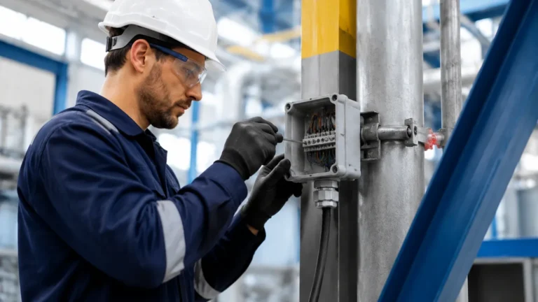
* Cable Glands: Always point cable entries downward to prevent moisture from entering the housing via the cable. Use a drip loop.
* Hazardous Areas: In environments with explosive dust or vapors, ensure the switch is rated for the specific zone (Ex d, Ex ia) and use appropriate safety barriers.

Limitations and Common Risks
While level switches are robust, they are not infallible. Recognizing their limitations is key to a reliable system.
* Material Buildup: In sticky or viscous applications, material can accumulate on the sensor. Vibrating forks have some self-cleaning capability due to the vibration, but heavy crusting will eventually dampen the signal. Capacitance switches with "active shield" technology can ignore buildup, but standard models may fail.
* Foam and Turbulence: Mechanical float switches and some ultrasonic switches may struggle with thick foam, either floating on top of it or failing to penetrate it. Vibrating forks are generally the best choice for ignoring foam in liquid applications.
* Specific Gravity Changes: Float switches depend on the density of the liquid. If the process changes from a heavy oil to a light solvent, the float may no longer have enough buoyancy to actuate the switch.
* Mechanical Wear: Rotary paddles and mechanical floats have moving parts. In abrasive environments (like mining or cement), these parts will wear down and require regular inspection.
Maintenance and Troubleshooting
To ensure long-term reliability, a preventative maintenance schedule should be implemented.
* Visual Inspection: Check for signs of corrosion on the wetted parts and moisture ingress in the electronics housing.
* Functional Test: Periodically simulate a high or low level to verify that the switch actuates and the control system responds correctly. This is often referred to as a "proof test."
* Cleaning: For applications prone to scaling or buildup, remove the switch and clean the sensing element with a compatible solvent or soft brush. Do not use abrasive tools on sensitive probe coatings.
Troubleshooting Common Issues
* Switch won't trigger: Check for power supply issues, obstructed floats, or material buildup that prevents movement/vibration.
* False alarms: Often caused by turbulence, foam, or electrical interference (EMI). Ensure the housing is properly grounded and the sensitivity settings (if applicable) are adjusted.
* Intermittent signals: Usually a sign of a loose wiring connection or a failing relay contact. Check the terminal block and cable integrity.
Frequently Asked Questions (FAQs)
Q: Can I use a liquid level switch for dry solids?
A: It depends on the technology. Vibrating forks designed for liquids have different frequencies than those for solids. Rotary paddles are strictly for solids. Generally, it is best to use a switch designed specifically for the media type.
Q: What is the difference between a NPN and PNP output?
A: These refer to the type of transistor used in DC switches. PNP (Positive-Negative-Positive) switches "source" power to the load, while NPN (Negative-Positive-Negative) switches "sink" the load to the ground. Your PLC input card type determines which one you need.
Q: How do I handle level switching in a pressurized tank?
A: You must ensure the switch's process connection (flange or thread) and the sensor body are rated for the maximum possible tank pressure. Magnetic level gauges with external switches are often used for high-pressure hazardous liquids to keep the electronics outside the pressure boundary.
Q: Is calibration required for level switches?
A: Most modern level switches (like vibrating forks) are factory-calibrated and "plug-and-play." However, capacitance switches usually require a one-time calibration to account for the tank's empty and full states.
Conclusion
Understanding how to level switches effectively is a balance of selecting the right physics for the media and ensuring the mechanical installation protects the sensor from process extremes. By following these guidelines on measurement principles and installation, engineers can significantly reduce the risk of overflows, dry runs, and equipment damage. For those seeking specific hardware for industrial automation or water treatment, exploring a comprehensive range of Level Switches is the next step in building a resilient process control system.