Keyboard Switch Levels
Keyboard Switch Levels
In the landscape of industrial automation, the term "keyboard switch levels" refers to the discrete setpoints and configuration parameters programmed into an electronic level switch via its local human-machine interface (HMI). While traditional mechanical switches rely on physical adjustments, modern electronic Level Switches utilize integrated keypads and digital displays to allow engineers to define precise actuation points, hysteresis, and delay times.
Understanding how to configure these keyboard switch levels is critical for maintaining process safety, preventing tank overflows, and ensuring pump protection. This guide explores the principles of level switching technology, the nuances of digital configuration, and the practical engineering considerations for selecting the right instrument for your application.
Principles of Level Measurement and Switching
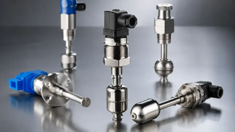
Before configuring keyboard switch levels, it is essential to understand the underlying physical principles that trigger the switch. Industrial level switches are categorized based on their sensing technology, each suited for specific media and environmental conditions.
1. Vibrating Tuning Fork Switches
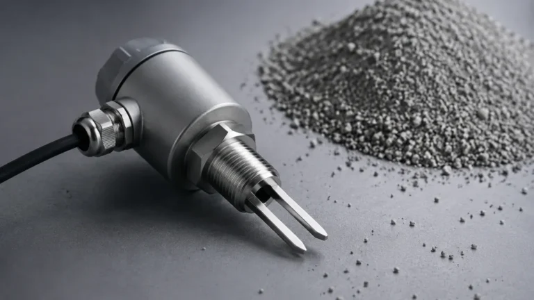
Vibrating level switches utilize a piezoelectric crystal to energize a tuning fork at its natural resonance frequency. When the fork is immersed in a liquid or solid, the frequency changes. The electronics detect this shift and trigger the switch output. Through the device keyboard, users can often adjust the sensitivity to account for varying material densities.
2. Ultrasonic Level Switches
Ultrasonic switches emit high-frequency sound waves. The time it takes for the pulse to return to the sensor determines the level. In these devices, "keyboard switch levels" are programmed as distance values (e.g., 2.0 meters from the sensor face) where the relay should toggle. These are ideal for non-contact applications.
3. Capacitance Level Switches
These sensors measure the change in electrical capacitance between the probe and the tank wall. As the medium rises, the dielectric constant changes. Configuration via the keyboard allows for "empty" and "full" calibration, defining the switching threshold based on the specific conductivity of the fluid.
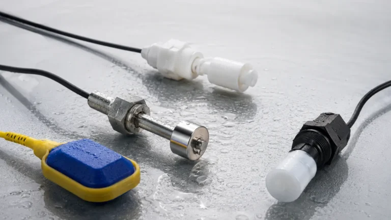
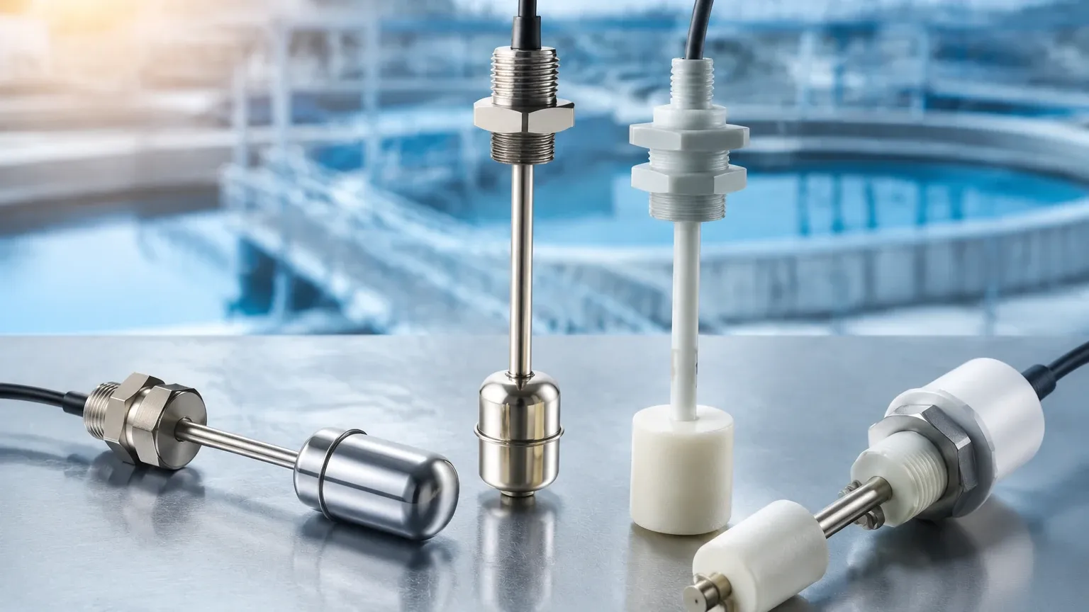
4. Float and Displacement Switches
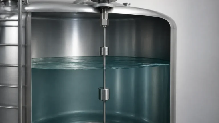
While primarily mechanical, many high-end float switches now include digital transmitters. The physical movement of a float triggers a magnetic reed switch or a microswitch. In digital variants, the keyboard interface allows the user to map these physical movements to digital alarm levels.
Configuring Keyboard Switch Levels: Key Parameters
When an engineer accesses the menu of a digital level switch, they are setting the logic that governs the process. The following parameters are standard across most professional-grade Welk instruments:
* Setpoint (SP): The exact level at which the switch changes state (e.g., from Open to Closed).
* Reset Point (RP): Also known as the release point, this is the level at which the switch returns to its original state.
* Hysteresis: The difference between the Setpoint and the Reset Point. This prevents "chattering," where the switch rapidly toggles on and off due to surface turbulence or ripples.
* Switching Logic: Configuration of Normally Open (NO) or Normally Closed (NC) states. For fail-safe applications, NC is often preferred so that a power failure triggers an alarm.
* Damping/Delay: A programmed time delay (usually 0 to 99 seconds) that requires the level to remain above the setpoint for a specific duration before the switch actuates. This is vital in tanks with high agitation.
Selection Table for Level Switch Technologies
Choosing the right technology depends on the media and the required precision. The table below provides a comparison of common technologies found in the Welk product line.
| Technology | Media Type | Temp. Range | Pressure Range | Keyboard Configurable? |
| :— | :— | :— | :— | :— |
| Tuning Fork | Liquids/Powders | -50°C to 150°C | Up to 40 bar | Yes (Sensitivity/Delay) |
| Ultrasonic | Clean Liquids | -40°C to 80°C | Atmospheric | Yes (Distance/Units) |
| Capacitance | Corrosive/Slurry | -40°C to 200°C | Up to 25 bar | Yes (Dielectric/Calib) |
| Hydrostatic | Deep Tanks/Wells | -20°C to 80°C | Up to 100m H2O | Yes (Zero/Span) |
| Magnetic Float| Clean Liquids | -10°C to 120°C | Up to 16 bar | Limited (Digital models) |
Practical Engineering Considerations
When defining keyboard switch levels for a project, several environmental and mechanical factors must be considered to ensure long-term reliability.
Media Characteristics
The viscosity, density, and dielectric constant of the medium directly impact how the switch perceives "level." For example, if a tuning fork switch is used in a highly viscous liquid (like heavy oil), the keyboard settings for sensitivity must be increased to ensure the fork can still vibrate effectively when the tank is empty.
Turbulence and Foam
Surface foam can cause false triggers in ultrasonic and radar-based switches. If foam is present, an engineer should use the keyboard interface to increase the damping or switch to a technology like a displacement or hydrostatic transmitter that is less affected by surface conditions.
Fail-Safe Requirements
In B2B industrial environments, safety is paramount. When setting up keyboard switch levels, the "fail-safe" direction must be determined.
* High Level Fail-Safe (MAX): The switch is energized when the level is below the setpoint. If power is lost or the level hits the limit, the switch de-energizes, triggering the alarm.
* Low Level Fail-Safe (MIN): The switch is energized when the level is above the setpoint. This is typically used for pump-dry protection.
Installation and Calibration Best Practices
Proper installation ensures that the values programmed via the keyboard reflect the actual physical state of the vessel.
1. Mounting Position: Ensure the sensor is not placed directly under a fill pipe. The falling liquid can cause false readings and physical damage to the probe.
2. Dead Zones: For ultrasonic switches, be aware of the "dead zone" (blocking distance) near the sensor face. The highest keyboard switch level must be set below this zone to avoid measurement errors.
3. Wiring and Grounding: Industrial level switches often operate in environments with significant electromagnetic interference (EMI). Use shielded cables and ensure the instrument is properly grounded to prevent "ghost" triggers in the electronics.
4. In-Situ Calibration: Whenever possible, perform a "wet calibration." Fill the tank to the desired alarm level and use the keyboard to capture that exact point as the setpoint. This accounts for any vessel irregularities or installation offsets.
Limitations and Maintenance
While digital Level Switches are highly versatile, they are not without limitations.
* Coating and Buildup: In applications involving wastewater or sticky chemicals, material can build up on the sensor. While some switches have "active shield" technology to ignore coating, periodic cleaning is necessary to maintain accuracy.
* Electronic Drift: Over years of operation, electronic components may experience slight drift. It is recommended to verify keyboard switch levels annually using a secondary reference measurement.
* Ambient Temperature: Extreme temperatures can affect the local LCD display and keyboard membrane. In outdoor installations in harsh climates (above 60°C or below -20°C), sunshades or heated enclosures may be required to keep the interface functional.
Frequently Asked Questions (FAQs)
Q: Can I set multiple switch levels on a single device?
A: Many modern electronic switches, especially ultrasonic and hydrostatic models, allow for multiple setpoints (e.g., SP1 for a warning and SP2 for a critical shutdown) via the keyboard menu.
Q: What is the difference between a level switch and a level transmitter?
A: A level switch provides a discrete output (on/off) at specific levels. A level transmitter provides a continuous signal (e.g., 4-20mA or RS485) representing the exact level. However, many transmitters include integrated switch functions where you can program keyboard switch levels for local relay control.
Q: How do I handle interface measurement (e.g., oil on water)?
A: Interface measurement usually requires specialized capacitance or guided wave radar switches. Through the keyboard, you must program the dielectric constants of both fluids to allow the sensor to distinguish between the two layers.
Q: Are these switches compatible with PLC systems?
A: Yes. Most digital level switches provide standard relay outputs (SPDT/DPDT) or PNP/NPN transistor outputs that interface directly with Programmable Logic Controllers (PLCs) or Distributed Control Systems (DCS).
Conclusion
The ability to precisely define keyboard switch levels has revolutionized tank management and process control. By moving away from purely mechanical adjustments, engineers can achieve higher accuracy, better repeatability, and enhanced safety. Whether you are managing water treatment facilities or complex chemical reactors, selecting a high-quality switch and properly configuring its digital setpoints is the foundation of a reliable automation strategy. For specific application support or to view technical specifications for various sensing technologies, you can explore the full range of industrial Level Switches designed for modern process demands.