Level Switch on P&id
Level Switch on P&id
In the field of industrial process engineering, the Piping and Instrumentation Diagram (P&ID) serves as the definitive blueprint for a plant’s functional logic. It illustrates the interconnection of process equipment and the instrumentation used to control the process. Among the most critical components depicted is the level switch, a device designed to detect the presence or absence of a substance at a specific height within a vessel or pipe. Understanding how to represent and interpret a level switch on p&id is essential for ensuring process safety, preventing overflows, and protecting equipment like pumps from running dry.
A level switch is a point-level measurement device, meaning it provides a binary output (on/off) rather than a continuous measurement of the level. On a P&ID, these devices are not just symbols; they represent specific engineering decisions regarding safety layers, automation logic, and hardware selection. This guide explores the technical standards, measurement principles, and practical selection criteria for integrating these instruments into industrial designs.
ISA S5.1 Identification and Symbols
The International Society of Automation (ISA) S5.1 standard provides the framework for instrument symbols and identification codes used on P&IDs. Every instrument is identified by a tag number, which consists of a series of letters and a loop number.
Letter Codes for Level Switches
For a level switch, the first letter is always "L" for Level. The second letter defines the function, which is "S" for Switch. A third (and sometimes fourth) letter is often added to indicate the state or setpoint of the switch:
* LSH (Level Switch High): Triggers an alarm or action when the level reaches a high point, typically used to prevent overfilling.
* LSL (Level Switch Low): Triggers when the level drops below a setpoint, often used to ensure a minimum volume for pump suction.
* LSHH (Level Switch High-High): Indicates a critical high level, often tied to an Emergency Shutdown (ESD) system.
* LSLL (Level Switch Low-Low): Indicates a critical low level, used for equipment protection to prevent catastrophic failure or dry running.
Graphical Representation
On a P&ID, the level switch is usually represented by a circle (often called a "bubble"). The lines drawn around or through the bubble indicate the instrument's location:
1. No line: The instrument is mounted in the field, near the process vessel.
2. Single solid horizontal line: The instrument is located in a primary control room or on a main control panel accessible to the operator.
3. Double solid horizontal line: The instrument is located in a secondary or local control panel.
4. Dashed horizontal line: The instrument is located behind a panel or in an inaccessible location.
When documenting a level switch on p&id, a line is drawn from the process vessel to the bubble. If the switch is directly mounted on the vessel, the bubble may touch the vessel wall or be connected by a short lead line. If the switch is part of a bypass chamber or external cage, this must be explicitly detailed to ensure correct mechanical installation.
Measurement Principles of Level Switches
Before an engineer can finalize the P&ID, the physical measurement principle must be selected based on the media properties (density, viscosity, conductivity) and process conditions (temperature, pressure). As a professional manufacturer, Welk provides various technologies to suit these diverse needs.
1. Vibrating Tuning Fork Level Switches
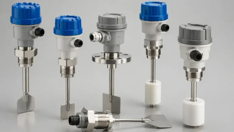
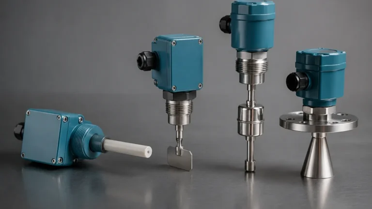
This technology utilizes a tuning fork that is vibrated at its resonant frequency by a piezoelectric crystal. When the fork is submerged in a liquid or covered by solids, the frequency changes. The internal electronics detect this shift and toggle the switch state. Tuning fork switches are highly reliable as they are unaffected by flow, turbulence, bubbles, or foam. They are commonly used for both LSH and LSL applications in water treatment and chemical processing.
2. Float and Magnetic Level Switches
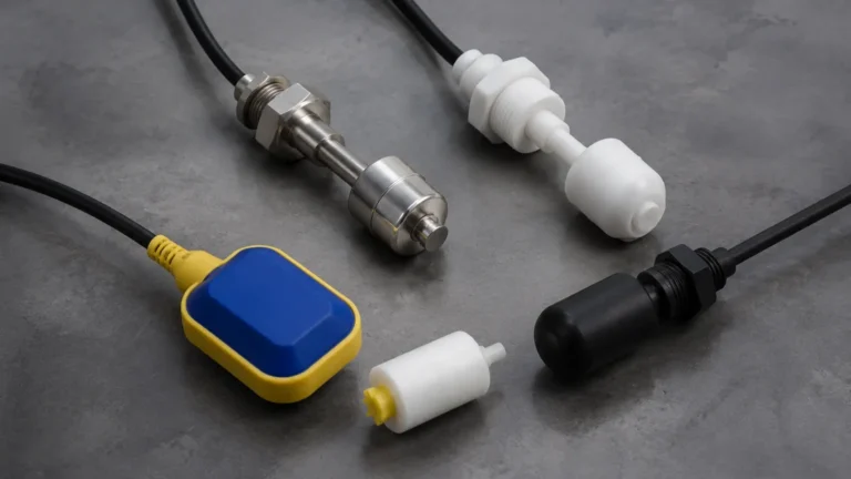
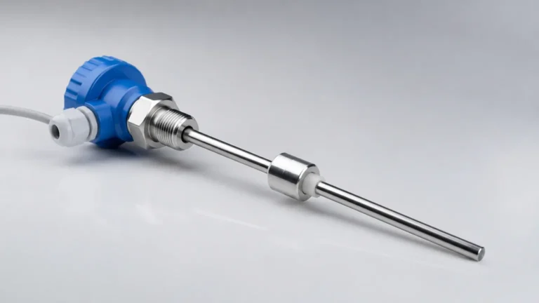
Float switches operate on the principle of buoyancy. A float containing a magnet moves with the liquid level. When the float reaches a predetermined point, the magnetic field actuates a reed switch or a microswitch. These are simple, cost-effective, and require no external power for the sensing element itself. They are frequently specified on P&IDs for oil-water separators and basic storage tanks.
3. Capacitance Level Switches
Capacitance switches measure the change in electrical capacitance between a probe and the vessel wall (or a reference electrode). As the process media covers the probe, the dielectric constant changes, altering the capacitance. These are ideal for detecting the interface between two liquids or for use with sticky substances, provided the probe is appropriately coated.
4. Ultrasonic Point Level Switches
Ultrasonic switches use high-frequency sound waves. A sensor emits a pulse that travels through a gap; when the gap is filled with liquid, the pulse is transmitted to a receiver. If the gap is filled with air or gas, the signal is attenuated. This non-contact or gap-sensing method is excellent for corrosive or high-purity liquids where mechanical movement is undesirable.
Selection Criteria for P&ID Design
Selecting the right technology is as important as the P&ID symbol itself. Engineers must evaluate the following factors to ensure the Level Switches perform as intended in the field.
Selection Table: Technology Comparison
| Technology | Media Type | Temp. Range | Pressure Range | Key Advantage |
| :— | :— | :— | :— | :— |
| Vibrating Fork | Liquids / Solids | -50°C to 250°C | Up to 64 bar | Maintenance-free, no calibration |
| Float Switch | Clean Liquids | -20°C to 150°C | Up to 40 bar | Simple, no power required |
| Capacitance | Liquids / Slurries | -40°C to 200°C | Up to 100 bar | Handles coating and buildup |
| Ultrasonic | Clean Liquids | -40°C to 100°C | Up to 20 bar | No moving parts, fast response |
| Rotary Paddle | Bulk Solids | -20°C to 80°C | Atmospheric | Robust for heavy powders/grains |
When specifying a level switch on p&id, the engineer should consider the "fail-safe" mode. For a high-level alarm (LSH), the switch should typically be "normally closed" (NC) so that a loss of power or a broken wire triggers the alarm, indicating a fault or a high level.
Installation Considerations and P&ID Details
The physical installation of a level switch must match the requirements of the measurement principle. A P&ID often includes small notations or references to "Installation Details" (standard drawings) to ensure the following are addressed:
* Nozzle Length and Diameter: For vibrating fork switches, the nozzle must be short enough to ensure the forks fully extend into the vessel. If the nozzle is too long, material may build up and cause a false trigger.
* Turbulence and Agitation: If the vessel has an agitator, the level switch must be positioned away from the blades and the resulting vortex. On the P&ID, this is sometimes indicated by placing the switch symbol on a specific side of the vessel.
* Stilling Wells and Bypass Chambers: For liquids with heavy turbulence or foaming, a float switch or tuning fork may be installed in a stilling well (a vertical pipe inside the tank) or an external bypass chamber. This is represented on the P&ID by a separate vertical line connected to the vessel at two points.
* Dead Zones: Every switch has a physical "dead zone" where it cannot detect level. This must be accounted for when setting the LSHH or LSLL setpoints to ensure there is enough time for the final control element (like a valve) to react.

Integration with Control Systems
The signal from a level switch is usually a discrete (digital) input to a PLC (Programmable Logic Controller) or DCS (Distributed Control System). On a P&ID, the connection between the level switch bubble and the control system is shown using specific line types:
* Solid Line: Mechanical or capillary connection.
* Dashed Line: Electrical signal (e.g., 24V DC contact).
* Line with Bubbles/Circles: Data link or software connection (e.g., Foundation Fieldbus or HART).
The P&ID should clearly show the logic resulting from the switch action. For example, a dashed line might lead from an LSHH bubble to a Solenoid Valve (XV) that shuts off the inlet flow. This visual representation of the "Interlock" is critical for safety audits and HAZOP (Hazard and Operability) studies.
Limitations and Common Risks
While level switches are fundamental to process control, they are not without limitations. Engineers must be aware of these risks during the design phase:
1. Material Buildup: In applications involving wastewater or viscous chemicals, material can accumulate on the sensing element. While capacitance and tuning fork switches offer some resistance to buildup, they may still require periodic cleaning.
2. Foam Interference: Some technologies, like ultrasonic or certain float designs, may struggle with thick foam, either triggering prematurely or failing to detect the liquid surface altogether.
3. Mechanical Wear: Float switches have moving parts that can seize over time due to corrosion or sediment. This is why critical safety loops (LSHH/LSLL) often prefer non-mechanical options like vibrating forks.
4. Density Changes: Buoyancy-based switches are calibrated for a specific specific gravity. If the process media changes (e.g., switching from oil to water), the switch point will shift.
To mitigate these risks, it is common practice to specify redundant switches on the P&ID for critical applications, using two different technologies to ensure diverse redundancy.
Frequently Asked Questions (FAQs)
What is the difference between a level switch and a level transmitter on a P&ID?
A level switch (LS) provides a point-level detection (on/off signal), whereas a level transmitter (LT) provides a continuous measurement (e.g., 4-20mA or 0-10V signal) of the actual level in the tank.
Why are there two switches (LSH and LSHH) at the top of a tank?
This is a safety-in-depth approach. The LSH (High) is typically used for a process alarm to alert the operator to stop the fill. The LSHH (High-High) is a safety interlock that automatically shuts down the pump or closes the inlet valve if the operator fails to respond to the LSH.
How do I show a wireless level switch on a P&ID?
According to ISA S5.1, wireless signals are often represented by a dashed line with a small zig-zag or radio wave symbol, or by using specific software signal lines that denote a wireless protocol.
Can a single device act as both LSH and LSL?
Some electronic switches have multiple setpoints or dual-probe configurations that allow them to monitor both high and low levels. On a P&ID, this would be shown as two bubbles (LSH and LSL) connected to a single process point, or a single bubble with multiple tag designations if the standard allows.
What does a line through the level switch bubble mean?
A single horizontal line through the center of the bubble indicates that the instrument's status or control is accessible to an operator in a primary control location (like a DCS screen). If there is no line, it is a local field instrument that must be checked physically at the tank.
By carefully selecting the appropriate technology and accurately documenting the level switch on p&id, engineers can ensure that industrial processes remain safe, efficient, and easy to maintain. For those in the procurement or design phase, reviewing the available Level Switches from specialized manufacturers like Welk is a critical step in matching technical specifications with real-world application demands.