Level Switch Pneumatic
Level Switch Pneumatic
In industrial process control, point level detection is a critical function for preventing tank overflows, protecting pumps from dry running, and managing automated filling cycles. While electronic sensors dominate many modern facilities, the level switch pneumatic remains a cornerstone technology in specific sectors, particularly where electrical power is unavailable, undesirable, or poses a significant safety risk. This guide explores the engineering principles, selection criteria, and practical applications of pneumatic level switches within the broader context of industrial Level Switches.
Understanding Pneumatic Level Detection Principles
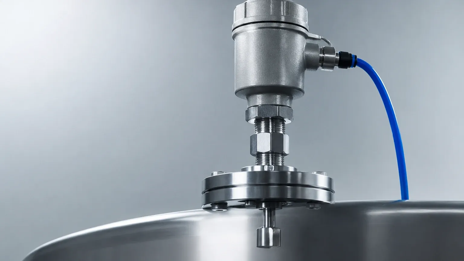
A pneumatic level switch is a mechanical device that utilizes a change in liquid level to actuate a pneumatic valve or relay, thereby altering an air signal. Unlike electronic switches that output a voltage or current change, these devices manipulate compressed air (typically instrument air) to signal a state change.
Mechanical Actuation and Pilot Valves
There are two primary mechanical methods used to trigger a pneumatic signal based on level:
1. Float-Operated Mechanisms: A buoyant float or displacer is submerged in the process media. As the liquid level rises or falls, the float moves a rod or linkage. This movement is transmitted to a pneumatic pilot valve. When the level reaches the predetermined set point, the linkage opens or closes the valve, allowing supply air to pass through to the output port or venting the output to the atmosphere.
2. Displacer-Operated Mechanisms: In higher pressure or more turbulent applications, a weighted displacer is used. Rather than floating on the surface, the displacer is heavier than the liquid. It relies on Archimedes' principle; as the liquid covers the displacer, the buoyant force reduces the effective weight of the displacer, which is sensed by a spring-loaded pneumatic relay.
The Pneumatic Signal
The output of a level switch pneumatic system is usually a discrete "on/off" air signal. In standard industrial pneumatic logic, this often translates to a change between 0 bar (0 psi) and the supply pressure, which is frequently regulated to approximately 1.4 bar (20 psi) or up to 7 bar (100 psi) depending on the control valve requirements. This signal can directly actuate a pneumatic control valve or trigger a pneumatic alarm horn.
Key Evaluation Criteria for Selection
Selecting the correct instrument requires a thorough understanding of the process environment. Engineers must evaluate several factors to ensure the level switch pneumatic performs reliably over its service life.
Media Characteristics
* Specific Gravity (SG): The buoyancy of the float or displacer is dependent on the density of the liquid. Most pneumatic switches are calibrated for a specific SG range (e.g., 0.5 to 1.5). If the liquid is too light, the float may not rise sufficiently to trigger the valve.
* Viscosity and Coating: Highly viscous liquids or those that tend to crystallize can impede the movement of mechanical linkages. In such cases, external cage designs or specialized coatings may be necessary.
* Corrosivity: The wetted parts (the float, rod, and process connection) must be compatible with the chemical nature of the fluid. Common materials include 316 Stainless Steel, Monel, or Hastelloy.
Process Conditions
* Pressure: Pneumatic switches are often used in pressurized separators or boilers. The housing and process connection must be rated for the maximum design pressure of the vessel.
* Temperature: High temperatures can affect the integrity of pneumatic seals (O-rings) within the pilot valve. Standard Viton or PTFE seals are common, but extreme temperatures may require extended neck designs to isolate the pneumatic head from the heat.
Air Supply Requirements
The reliability of a pneumatic switch is only as good as the air supply powering it. The air must be clean, dry, and regulated. Moisture in the air line can lead to corrosion or freezing in cold climates, while oil or particulate matter can clog the small orifices in the pilot valve.
Comparison: Pneumatic vs. Electric Level Switches
| Feature | Pneumatic Level Switch | Electric Level Switch |
| :— | :— | :— |
| Primary Power | Compressed Air / Instrument Air | AC/DC Electricity |
| Hazardous Areas | Inherently safe; no spark risk | Requires explosion-proof housing or IS barriers |
| Output Signal | Air pressure (0-100 psi) | Relay contact, PNP/NPN, or mA |
| Installation Complexity | Requires pneumatic tubing | Requires electrical conduit and wiring |
| Maintenance | Seal replacement, air filter checks | Contact wear, moisture in housing |
| Remote Locations | Ideal for sites with air but no power | Difficult without solar/battery systems |
Installation and Calibration Considerations
Proper installation is paramount for the mechanical integrity of a level switch pneumatic. Because these devices rely on physical movement, alignment and stability are critical.
Mounting Configurations
* Side Mounting: The switch is installed through a flange or NPT connection on the side of the tank. This is common for high or low-level alarms. It is essential to ensure the float has enough clearance to move through its full arc without hitting the tank wall or internal baffles.
* Top Mounting: Used when side access is restricted. These typically utilize a long rod and a vertical float or displacer. For deep tanks, stilling wells are recommended to prevent the rod from bending due to fluid turbulence.
* External Cage: The switch is mounted in a separate chamber piped to the side of the vessel. This allows for maintenance and testing without depressurizing the main vessel and provides a more stable liquid level for the float.
Air Line Connection
When plumbing the level switch pneumatic, use high-quality stainless steel or copper tubing. Plastic tubing is susceptible to environmental degradation and mechanical damage. A local filter-regulator should be installed as close to the switch as possible to ensure the pilot valve receives air at the correct pressure and purity.
Calibration Procedure
Most pneumatic switches allow for field adjustment of the set point. This is typically done by adjusting the tension on a range spring or moving the position of the float on the rod. To calibrate:
1. Ensure the vessel is at a safe level.
2. Connect a pressure gauge to the output port.
3. Manually raise or lower the level (or simulate it using the mechanical linkage).
4. Adjust the set point screw until the output signal switches at the desired level.
5. Repeat the process to verify repeatability and check for deadband (hysteresis).
Limitations and Maintenance Challenges
While robust, pneumatic level switches have specific limitations that engineers must manage.
Air Consumption and Bleeding
Many pneumatic pilot valves are "bleeding" types, meaning they consume a small amount of air even when in a steady state. In large facilities with hundreds of switches, this cumulative air consumption can be significant. Non-bleeding or "snap-acting" relays are preferred to minimize air waste and reduce the load on the compressor system.
Response Time
Pneumatic signals travel at the speed of sound through the air, which is significantly slower than electrical signals. For very long distances (over 100 meters), the time delay between the level switch triggering and the final control element reacting can be several seconds. This lag must be accounted for in the safety logic of the plant.
Seal Wear
The dynamic seals within the pneumatic relay are subject to wear over time. Friction and environmental contaminants can cause seals to leak or stick. A preventative maintenance schedule should include periodic testing of the switch and inspection of the air exhaust ports for signs of bypass leakage.
Industrial Applications for Pneumatic Level Switches
Oil and Gas Production
In upstream oil and gas, pneumatic switches are ubiquitous. Wellhead separators often operate in remote locations where electrical infrastructure is non-existent. These separators use pneumatic switches to control the dump valves that manage the water and oil interfaces. The inherent explosion-proof nature of pneumatics is a major advantage in these high-hydrocarbon environments.
Chemical Processing
Facilities handling highly flammable or explosive chemicals often prefer pneumatic logic for critical safety interlocks. By removing electricity from the sensing point, the risk of an accidental spark leading to a fire is eliminated. Furthermore, pneumatic systems are often more resilient to the Electromagnetic Interference (EMI) found in heavy industrial plants.
Water and Wastewater
In remote pump stations or reservoirs, pneumatic bubbler systems (a variation of pneumatic level sensing) are used to monitor levels in open sumps. These systems use a constant flow of air through a tube; the pressure required to push air out of the tube corresponds to the liquid head. A pneumatic pressure switch then acts as the level switch pneumatic to start or stop pumps.
Frequently Asked Questions (FAQs)
Q: Can a pneumatic level switch be used for continuous level measurement?
A: Standard pneumatic level switches are point-level devices (on/off). However, pneumatic level transmitters exist that provide a proportional 0.2 to 1.0 bar (3-15 psi) signal for continuous monitoring.
Q: What happens if the air supply fails?
A: This depends on the configuration. Most systems are designed to be "fail-safe." For example, a high-level switch might be configured so that a loss of air pressure triggers the same action as a high-level condition (e.g., closing a feed valve).
Q: Are pneumatic switches compatible with digital control systems (DCS)?
A: Yes, but they require a P/I (Pressure-to-Current) transducer. This device converts the pneumatic signal into a 4-20mA signal that the DCS can interpret. Alternatively, the pneumatic signal can actuate a local pressure switch with electrical contacts.
Q: How do I prevent the pneumatic lines from freezing?
A: The most effective method is to use a desiccant air dryer at the compressor source to ensure the dew point of the instrument air is well below the lowest ambient temperature. In extreme cases, heat tracing on the pneumatic lines may be required.
Conclusion
The level switch pneumatic remains a vital tool for industrial automation, offering unmatched safety in hazardous areas and reliability in remote locations. By understanding the mechanical principles of buoyancy and pneumatic relay logic, engineers can specify and maintain these systems to ensure long-term operational safety. Whether used in an offshore oil platform or a chemical refinery, these devices provide a robust alternative to electronic Level Switches when environmental or safety constraints demand a non-electric solution.