Rotary Level Switches
Rotary Level Switches
In the field of industrial bulk solids management, ensuring that silos, hoppers, and bins do not overflow or run empty is a fundamental requirement for process efficiency and safety. Among the various technologies available for point level detection, rotary level switches remain one of the most widely utilized and reliable solutions. These mechanical instruments are specifically engineered to detect the presence or absence of dry bulk materials, ranging from fine powders like flour to heavy aggregates like gravel.
As part of a broader category of Level Switches, the rotary paddle design offers a robust alternative to electronic sensors in environments where dust, dielectric constant variations, or high temperatures might interfere with non-contact or capacitance-based measurements. This guide explores the mechanical principles, application criteria, and installation best practices for rotary level switches in modern industrial automation.
Measurement Principles and Internal Mechanics
The operation of a rotary level switch is based on a relatively simple yet highly effective mechanical principle: the detection of torque resistance. Unlike ultrasonic or radar sensors that use wave propagation, a rotary switch interacts physically with the process material.
The Drive Mechanism
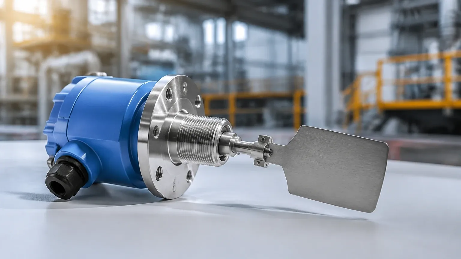
At the core of the device is a low-speed synchronous motor, typically rotating at approximately 1 RPM (revolution per minute). This motor is connected to an internal shaft that extends into the vessel, terminating in a paddle (or vane). Under normal conditions, when the material level is below the paddle, the motor rotates the shaft and paddle freely.
The Switching Action
When the material level rises and reaches the paddle, the physical resistance of the bulk solid impedes the paddle's rotation. This creates a counter-torque. Inside the housing, the motor is mounted on a pivot or a spring-loaded mechanism. As the paddle is stalled, the motor itself begins to rotate around the shaft axis, tripping a microswitch. This action performs two simultaneous functions:
1. Signal Output: It switches the electrical contact (SPDT or DPDT), sending a signal to a PLC, alarm, or motor starter to indicate a "full" or "covered" state.
2. Motor Protection: It cuts power to the motor itself, preventing the motor from burning out while the paddle is stalled by the material.
Resetting the Switch
Once the material level drops and the paddle is no longer obstructed, a torsion spring pulls the motor back to its original position. This releases the microswitch, restores power to the motor, and the paddle begins to rotate again, indicating an "empty" or "uncovered" state.
Key Components and Variations
To accommodate different material densities and vessel geometries, rotary level switches are available in several configurations. Understanding these components is essential for selecting the correct instrument for a specific application.
Paddle Designs
The shape and surface area of the paddle determine the switch's sensitivity to different bulk densities. Common designs include:
* Standard Vane: A rectangular paddle used for general-purpose powders and granules.
* Scimitar/Sickle Paddle: Shaped to allow the switch to be threaded into a mounting nozzle without removing the paddle, ideal for retrofitting.
* Large Vane: Used for very light, low-density materials (e.g., plastic flakes or sawdust) where more surface area is needed to generate sufficient torque.
* Multi-vane/Cross Paddle: Provides higher resistance for heavy materials like ores or stones.
Housing and Enclosures
Industrial environments often involve dust and moisture. Most rotary level switches feature aluminum or reinforced plastic housings with IP65 or IP66 ratings. In industries handling combustible dust (such as grain or coal), explosion-proof enclosures (ATEX/IECEx certified) are mandatory to prevent the internal electrical components from becoming an ignition source.
Shaft Extensions and Guards
While standard switches have a short shaft (typically 100 mm to 150 mm), some applications require the switch to reach deeper into a silo. Extension shafts can reach up to 3 meters. In high-impact environments, a protective guard or "pipe extension" is used to shield the shaft from the weight and lateral force of falling material.
Practical Selection Criteria
Selecting the right rotary level switch requires an analysis of the material properties and the physical environment of the container. The following table provides a general guideline for matching material types with switch configurations.
Selection Table: Material and Configuration
| Material Type | Typical Bulk Density (kg/m³) | Recommended Paddle | Sensitivity Setting |
| :— | :— | :— | :— |
| Plastic Pellets | 450 – 600 | Standard Vane | Medium |
| Cement / Fly Ash | 1,000 – 1,500 | Standard Vane | High |
| Grain (Corn/Wheat) | 600 – 800 | Scimitar Paddle | Medium |
| Wood Chips / Flakes | 150 – 300 | Large Vane | High |
| Gravel / Aggregates | 1,600 – 2,400 | Heavy Duty Cross | Low |
| Flour / Fine Powder | 400 – 550 | Standard Vane | High |
Sensitivity Adjustment
Most professional-grade rotary level switches, such as those manufactured by Welk, include an adjustable torsion spring. By changing the spring tension, the operator can calibrate how much torque is required to trip the switch. This is crucial for very light materials where a stiff spring might prevent the switch from ever triggering.
Installation Considerations
The longevity and accuracy of rotary level switches depend heavily on correct placement. Improper installation is the leading cause of mechanical failure in these devices.
1. Avoiding the Filling Stream
The paddle should never be placed directly in the path of falling material. The force of the material stream can bend the shaft or cause premature wear on the motor bearings. If the switch must be near an inlet, a protective baffle (V-shaped metal plate) should be installed above the paddle to deflect the flow.
2. Mounting Orientation
* Top Mounting: The switch is installed vertically through the roof of the silo. This is common for high-level detection. For long distances, a flexible cable extension may be used instead of a rigid shaft to prevent bending.
* Side Mounting: The switch is installed horizontally through the side wall. This is common for low-level or mid-level detection. In this orientation, it is vital to ensure the cable entry points downward to prevent moisture from entering the housing through the conduit.
3. Nozzle Length
When mounting through a nozzle, ensure the paddle extends fully into the vessel. If the paddle is partially shrouded by the mounting nozzle, material may become trapped in the nozzle (caking), preventing the paddle from rotating or causing a false "full" signal.
4. Wiring and Power
Ensure the supply voltage matches the motor specification (e.g., 24V DC, 110V AC, or 230V AC). It is recommended to use a delayed relay in the control system if the material is prone to turbulence, which prevents "chattering" of the switch contacts.
Limitations and Comparison with Other Technologies
While rotary level switches are versatile, they are not suitable for every scenario. Engineers should be aware of their technical boundaries:
* Mechanical Wear: Because they have moving parts, the motor and seals will eventually wear out. In applications with extremely abrasive materials or high-cycle frequencies, a non-mechanical sensor like a vibrating rod or tuning fork might be preferred.
* Material Buildup: Sticky or cohesive materials (like wet clay) can build up on the paddle. If the weight of the buildup becomes too great, the switch may stay in the "full" position even after the silo is empty.
* Not for Liquids: Rotary switches are designed for solids. In liquids, the viscosity is usually insufficient to stall the motor, and the seals are not typically rated for hydrostatic pressure immersion.
* Point Level Only: These devices only provide a binary signal (on/off). For continuous level measurement (0-100%), radar or ultrasonic transmitters are required.
Maintenance and Troubleshooting
One of the primary advantages of the rotary design is that it is often field-repairable. Welk provides modular replacement parts, including motors and microswitches, to extend the service life of the instrument.
* Routine Inspection: Check the paddle for signs of bending or erosion every 6 to 12 months, especially in abrasive applications.
* Seal Integrity: Inspect the shaft seal. If fine dust has penetrated the housing, the seal should be replaced to prevent damage to the internal gears.
* Testing: Most units feature a test button or a way to manually stall the paddle to verify that the control circuit is receiving the signal.
Frequently Asked Questions (FAQ)
Q: Can a rotary level switch be used for very light materials like expanded polystyrene (EPS)?
A: Yes, but it requires a large-diameter paddle and the internal torsion spring must be set to the lowest sensitivity (weakest tension) to ensure the light material can stop the motor.
Q: What is the maximum temperature a rotary switch can handle?
A: Standard models usually handle up to 80°C. However, high-temperature versions with thermal spacers and specialized seals can operate in environments up to 250°C or higher.
Q: How do I prevent the motor from burning out if the paddle is stuck for a long time?
A: Quality rotary level switches are designed to automatically cut power to the motor once the microswitch is triggered. The motor only consumes power when the paddle is actually rotating.
Q: Is it possible to change the paddle without replacing the whole unit?
A: Yes. Most shafts use a standard pin or threaded connection, allowing paddles to be swapped based on the material density of the current process.
By understanding the mechanical requirements and environmental constraints of the application, engineers can effectively implement rotary level switches as a cost-effective and dependable component of their level control strategy. For more complex requirements involving liquids or continuous monitoring, exploring the full range of Level Switches and transmitters is recommended to ensure the highest level of process reliability.