Level Switch Symbol
Level Switch Symbol
In industrial automation and process control, the accurate representation of instrumentation on technical drawings is fundamental to engineering safety, installation accuracy, and maintenance efficiency. The level switch symbol serves as the universal language between design engineers, electricians, and maintenance technicians. Whether appearing on a Piping and Instrumentation Diagram (P&ID) or an electrical schematic, these symbols convey critical information about the device's function, its physical state, and its role in the control logic.
As a professional manufacturer of industrial level measurement instruments, Welk provides a wide range of Level Switches designed for diverse applications, from water treatment to chemical processing. Understanding how to interpret and apply the correct level switch symbol is the first step in integrating these essential components into a reliable industrial system.
Fundamental Principles of Level Switches
Before diving into the specifics of symbols, it is essential to understand the underlying measurement principles. Different technologies are represented by varying notations, and the choice of technology dictates the performance of the switch in specific environments.
Float Level Switches
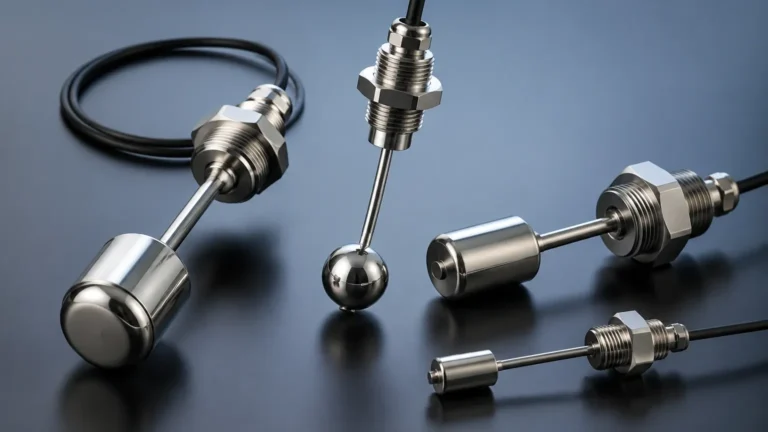
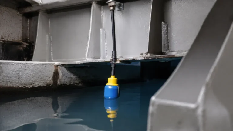
Float switches operate on the principle of buoyancy. A float, containing a magnet, moves with the liquid level. When the float reaches a predetermined point, the magnetic field triggers a reed switch or a microswitch. These are simple, cost-effective, and widely used for basic high or low-level alarms in non-viscous liquids.
Vibrating Level Switches (Tuning Fork)
Vibrating switches, often called tuning fork switches, use an electronic circuit to energize a pair of forks at their resonant frequency. When the forks are covered by a medium (liquid or solid), the frequency changes. This change is detected by the electronics and converted into a switching signal. These are highly versatile and resistant to turbulence and bubbles.
Capacitance Level Switches
Capacitance switches detect the change in electrical capacitance between a probe and the tank wall (or a reference electrode). As the medium displaces air, the dielectric constant changes, altering the capacitance. These are ideal for both conductive and non-conductive materials but require calibration based on the specific gravity and dielectric properties of the medium.
Conductivity Level Switches
These switches utilize the electrical conductivity of the liquid. When the liquid touches the probe, a small electrical current flows between the probe and the tank wall (or another probe), completing a circuit. This technology is limited to conductive liquids like water or acids.
Understanding the Level Switch Symbol in P&ID
The Piping and Instrumentation Diagram (P&ID) is the primary document used to define the process flow and the control system. The level switch symbol in a P&ID follows standards set by the International Society of Automation (ISA), specifically ISA 5.1.
The Instrument Bubble
In a P&ID, every instrument is represented by a circle, often called a "bubble." The lines drawn through or around the bubble indicate the location of the device:
- No line: Field-mounted (directly on the tank or pipe).
- Single solid horizontal line: Mounted in a primary control room/panel accessible to the operator.
- Double solid horizontal line: Mounted in a secondary or local panel.
- Dashed horizontal line: Mounted in a location not normally accessible to the operator (e.g., inside a cabinet).
Letter Designations
Inside the bubble, a series of letters identifies the function. For level switches, the standard format is:
- L: Level (The measured variable).
- S: Switch (The function of the instrument).
- H / L: High or Low (The state or setpoint).
Common combinations include:
- LSH: Level Switch High (Used for high-level alarms or pump stops).
- LSL: Level Switch Low (Used for low-level alarms or pump starts).
- LSHH: Level Switch High-High (Indicates an emergency overfill condition).
- LSLL: Level Switch Low-Low (Indicates an emergency low-level condition to prevent pump cavitation).
Connectivity Lines
The lines connecting the bubble to the process represent the physical connection (e.g., a process flange), while the lines leading away from the bubble represent the signal type. A solid line with cross-hatches usually denotes a pneumatic signal, while a dashed line represents an electrical signal (4-20mA or digital contact).
Electrical Schematic Symbols for Level Measurement
While P&IDs focus on the process function, electrical schematics focus on the wiring and circuit logic. The level switch symbol in an electrical drawing follows IEC 60617 or ANSI/IEEE standards.
Contact States: NO and NC
The most critical aspect of an electrical level switch symbol is the contact state:
- Normally Open (NO): The circuit is open when the switch is in its "normal" state (usually empty or at the bottom of its travel). The circuit closes when the level reaches the setpoint.
- Normally Closed (NC): The circuit is closed in the normal state and opens when the level reaches the setpoint.
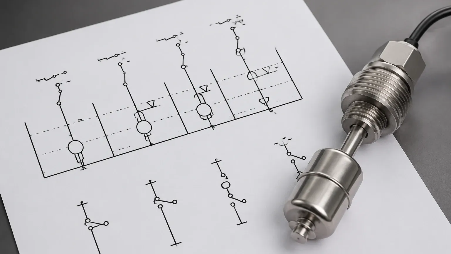
In a schematic, a level switch is often depicted as a standard switch contact with a small "flag" or "float" icon attached to the arm. The orientation of this icon indicates whether it is a high-level or low-level switch.
Logic Representation
In modern PLC (Programmable Logic Controller) ladder logic, the level switch is represented as a digital input. The symbol used here is typically a set of parallel lines (for NO) or parallel lines with a slash (for NC). The "level switch symbol" in this context is purely digital, but it must correspond exactly to the physical wiring of the device in the field.
Practical Selection and Application Table
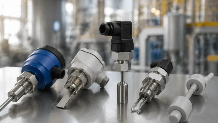
Choosing the right switch and documenting it correctly requires a comparison of technologies. The following table provides a reference for selecting Welk level switches based on application needs.
| Technology | P&ID Symbol | Best For | Temperature Range | Pressure Range | Limitations |
| :— | :— | :— | :— | :— | :— |
| Float Switch | LSH / LSL | Clean liquids, water tanks | -20°C to 120°C | Up to 20 bar | Susceptible to coating and debris. |
| Tuning Fork | LSH / LSL | Slurries, powders, aerated liquids | -40°C to 150°C | Up to 40 bar | Not for very high viscosity materials. |
| Capacitance | LSH / LSL | Non-conductive oils, chemicals | -50°C to 200°C | Up to 60 bar | Requires calibration for dielectric changes. |
| Conductivity | LSH / LSL | Acids, wastewater, conductive fluids | 0°C to 100°C | Atmospheric | Requires conductive medium; probe fouling. |
| Hydrostatic | LSH / LSL | Deep tanks, wells | -20°C to 80°C | Dependent on cable length | Sensitive to density changes. |
Installation and Engineering Considerations
Correctly identifying the level switch symbol on a drawing is only half the battle; the physical installation must mirror the design intent to ensure the symbol's function is realized.
Mounting Orientation
Level switches can be side-mounted (horizontal) or top-mounted (vertical). The symbol on the P&ID usually shows the connection point. For side-mounted switches, ensure there is at least 50 mm (approx. 2 inches) of clearance from internal tank structures like baffles or agitators.
Avoiding Turbulent Zones
If a level switch is placed near a liquid inlet, the turbulence may cause the switch to "chatter" (rapidly open and close). In such cases, the engineering drawing should specify a stilling well. The level switch symbol remains the same, but a note is often added to the P&ID indicating the use of a bypass pipe or stilling well.
Wiring and Grounding
For capacitance and conductivity switches, proper grounding is essential. The electrical schematic should show the ground symbol connected to the instrument housing or the tank wall. Failure to follow the grounding requirements shown in the electrical level switch symbol documentation can lead to signal noise and false triggering.
Limitations and Maintenance
Every level measurement technology has physical boundaries that must be respected, regardless of how they are documented.
1. Coating and Buildup: In applications involving sticky resins or wastewater, material can build up on the probe. While tuning fork switches are somewhat resistant, float switches will eventually fail. Maintenance schedules should be based on the "Criticality" indicated by the LSHH or LSLL symbols.
2. Specific Gravity: Float switches are designed for a specific range of liquid densities. If the medium changes (e.g., switching from water to a light oil), the float may no longer trigger at the correct level, rendering the LSH symbol on the drawing inaccurate.
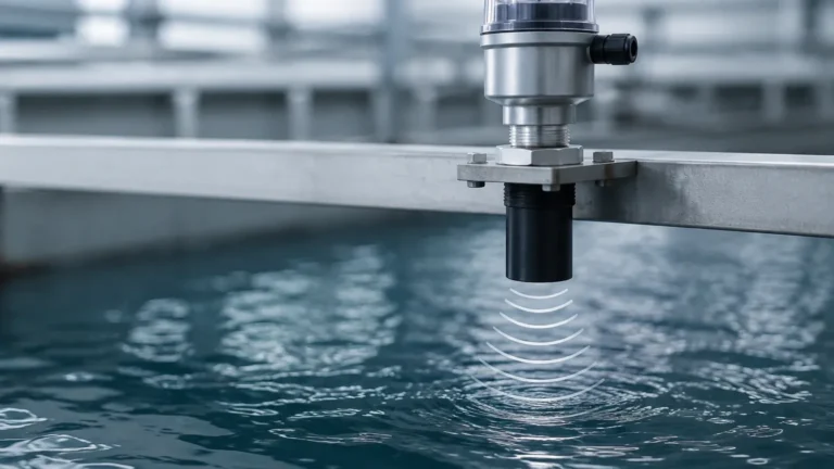
3. Foam and Bubbles: Ultrasonic and some capacitance switches may struggle with heavy foam. In these instances, a tuning fork switch is often the preferred technical solution.
Frequently Asked Questions
What is the difference between an LSH and an LSHH symbol?
LSH (Level Switch High) is typically used for process control, such as stopping a pump when a tank is full. LSHH (Level Switch High-High) is a safety-critical symbol representing an independent emergency switch that triggers an alarm or a Safety Instrumented System (SIS) to prevent environmental spills or tank rupture.
Does the level switch symbol change for solids vs. liquids?
In P&ID standards, the letter "L" is used for both liquids and bulk solids (like grain or plastic pellets). However, the underlying technology (e.g., a rotating paddle switch for solids vs. a float for liquids) will be specified in the instrument data sheet associated with that symbol.
How do I represent a multi-point level switch?
For a single probe that has multiple switching points (e.g., a float rod with three internal reed switches), the P&ID may show one bubble with multiple designations like "LSL/H/HH" or multiple bubbles connected to a single process point.
Why is the "Normally Closed" (NC) contact preferred for safety?
In safety-critical applications, NC contacts are preferred because they are "fail-safe." If a wire breaks or power is lost, the circuit opens, which the control system interprets as a trip condition. The electrical level switch symbol should clearly indicate if the logic is fail-safe.
By adhering to standardized symbols and understanding the technical principles behind them, engineers can ensure that the Level Switches provided by Welk are installed and operated with the highest degree of precision. Whether you are designing a new water treatment facility or upgrading a chemical storage farm, the level switch symbol remains the cornerstone of clear and effective process communication.