3 Position Lever Switch
3 Position Lever Switch
In the complex landscape of industrial automation and fluid management, the 3 position lever switch serves as a critical interface between manual oversight and automated sensing. While advanced Level Switches provide the continuous data and discrete signals required for high-precision monitoring, the physical lever switch allows operators to dictate the operational state of pumps, valves, and alarms. This guide explores the engineering principles, integration strategies, and selection criteria for utilizing 3 position lever switches within industrial level control systems.
Understanding the Role of 3 Position Lever Switches in Level Control
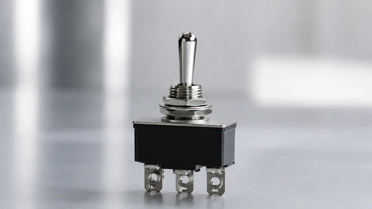
In most industrial level measurement applications, a 3 position lever switch is configured as a "Hand-Off-Auto" (HOA) selector. This configuration is essential for maintaining system flexibility and safety. The principle of operation relies on three distinct contact states:
1. Hand (Manual): In this position, the lever switch bypasses the automated level sensors. The circuit is closed directly to the motor starter or actuator, allowing the pump or valve to run regardless of the fluid level. This is typically used for testing, priming, or emergency drainage.
2. Off: The center position breaks all control circuits. Even if the automated level switches signal a high or low condition, the final control element remains inactive. This is a vital safety state for maintenance and system shutdowns.
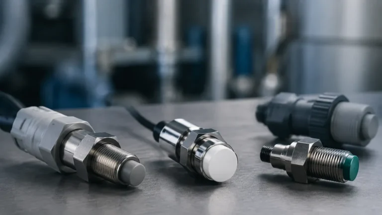
3. Auto (Automatic): This position hands control over to the primary sensing instrumentation. In this mode, the system relies on the signals generated by point-level sensors, such as float switches, ultrasonic sensors, or tuning fork level switches, to start and stop processes based on predefined setpoints.
The integration of a 3 position lever switch ensures that the sophisticated logic provided by modern measurement instruments can be overridden by human intervention when process conditions deviate from the norm.
Types and Configurations of Lever Switches
Selecting the correct 3 position lever switch requires an understanding of the internal contact blocks and the mechanical action of the lever. Industrial switches are categorized by their mounting diameter—typically 22 mm or 30 mm—and their environmental sealing ratings.
Maintained vs. Momentary Action
For level control, "maintained" switches are the standard. A maintained 3 position lever switch stays in the position to which it is moved. In contrast, a "momentary" or "spring-return" switch will return to the center (Off) position once the operator releases the lever. Spring-return configurations are occasionally used in "Hand" positions to prevent a pump from being left running unattended in manual mode.
Contact Block Logic
The electrical behavior is determined by the arrangement of Normally Open (NO) and Normally Closed (NC) contacts. A standard HOA setup utilizes two sets of NO contacts. When the lever is moved to the left (Hand), the first set closes. When moved to the right (Auto), the second set closes. In the center (Off) position, both sets remain open.
Integrating Level Switches with Manual Control Interfaces
The effectiveness of a control panel depends on how well the manual 3 position lever switch communicates with the primary Level Switches. In a typical water treatment or chemical processing application, the "Auto" terminal of the lever switch is wired in series with the output relay of the level sensor.
For example, in a tank filling application:
* The Level Switch is installed at the high-level setpoint (e.g., 5000 mm from the tank floor).
* The 3 Position Lever Switch is set to "Auto."
* When the fluid reaches the sensor, the level switch opens its contact, breaking the circuit that was energized through the lever switch's "Auto" position, thereby stopping the pump.
This synergy allows for high-reliability automation while providing the operator with a physical "Off" state for lock-out/tag-out (LOTO) procedures and a "Hand" state for manual overrides during sensor calibration or tank cleaning.
Selection Criteria for Industrial Control Switches
When specifying a 3 position lever switch for a level control project, engineers must evaluate the following technical parameters to ensure compatibility with the operating environment.
| Feature | Specification Requirement | Application Context |
| :— | :— | :— |
| Mounting Diameter | 22.5 mm or 30.5 mm | Standard industrial panel cutouts. |
| Ingress Protection | IP65, IP66, or IP67 | Resistance to dust and moisture in wash-down areas. |
| Contact Rating | 10A @ 240V AC / 2.5A @ 125V DC | Must match the inrush current of the control relay. |
| Material | Chrome-plated metal or Polyamide | Metal for impact resistance; plastic for corrosive chemical environments. |
| Operating Temperature | -25°C to +70°C | Essential for outdoor installations in oil and gas fields. |
| Mechanical Life | >1,000,000 cycles | Ensures longevity in high-frequency switching applications. |
Installation and Wiring Considerations
Proper installation of a 3 position lever switch is paramount to system safety. In industrial environments, wiring should follow local electrical codes (such as NEC or IEC standards).
1. Enclosure Selection: Lever switches should be mounted in NEMA 4X or IP66 rated enclosures if they are located near tanks where splashing or corrosive vapors are present.
2. Conduit Entry: Always use bottom-entry conduits with proper cable glands to prevent moisture from traveling down the wires and onto the contact blocks.
3. Grounding: Ensure the metal operator body is properly grounded to the panel backplate to prevent static buildup or electrical shock hazards.
4. Labeling: Clear, permanent legend plates (Hand-Off-Auto) must be installed to prevent operator error, which is a leading cause of tank overflows in manual mode.
In systems utilizing conductive fluids or hazardous chemicals, the lever switch is often part of an intrinsically safe circuit. In these cases, the switch must be wired through a galvanically isolated barrier before connecting to the level sensors located in the hazardous zone.
Common Applications and Limitations
Applications
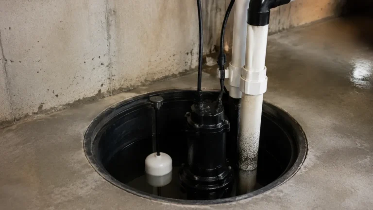
* Sump Pump Control: Managing wastewater levels where manual override is needed to clear debris.
* Chemical Batching: Allowing operators to manually top off a tank after an automated cycle.
* Cooling Towers: Switching between automated makeup water control and manual bypass during winterization.
Limitations
Despite their utility, 3 position lever switches have inherent limitations. They are mechanical devices subject to wear and tear. Over time, contact resistance can increase, leading to intermittent signals in the "Auto" circuit. Furthermore, a lever switch provides no inherent logic; it cannot prevent a pump from running dry if the operator leaves it in the "Hand" position. To mitigate this risk, it is recommended to pair the lever switch with a secondary low-level safety cutoff switch that remains active even in manual mode.
Frequently Asked Questions (FAQs)
Q: Can a 3 position lever switch replace an automated level switch?
A: No. A lever switch is a manual interface. An automated level switch (such as a radar or ultrasonic sensor) is required to detect the actual fluid level and provide the signal for the "Auto" mode.
Q: What is the difference between a 2-position and a 3-position switch in level control?
A: A 2-position switch typically only offers "On-Off" or "Manual-Auto." A 3-position switch adds the critical "Off" center position, which ensures that neither the manual nor the automatic circuit is energized, providing a safer environment for maintenance.
Q: How do I choose between a metal and a plastic lever switch?
A: Metal switches are preferred for heavy industrial environments where physical impact is likely. Plastic (polyamide) switches are superior in chemical processing plants where acidic or alkaline vapors might corrode metal components.
Q: Is it possible to have a 3 position switch with a key lock?
A: Yes. Key-operated 3 position switches are often used when access to the "Hand" or "Auto" modes must be restricted to authorized personnel to prevent unauthorized process changes.
For engineers designing comprehensive level management systems, selecting the right manual interface is as important as choosing the primary Level Switches. By combining robust mechanical switches with precise electronic sensors, facilities can achieve a balance of automated efficiency and reliable manual control.