Level Switch a 01 041
Level Switch a 01 041
In the field of industrial automation and fluid management, point-level detection serves as a critical safeguard for equipment protection and process control. Among the various components utilized for these tasks, the level switch a 01 041 represents a specific category of magnetic float switches designed for reliable, repeatable performance in relatively clean liquid environments. Understanding the operational mechanics, material compatibility, and installation requirements of such devices is essential for engineers tasked with maintaining system integrity in hydraulic power units, cooling systems, and chemical processing tanks.
Industrial Level Switches function as binary sensors, providing an "on/off" signal when a liquid reaches a predetermined height. Unlike continuous level transmitters that provide a constant data stream (such as 4-20mA or Modbus), a point-level switch is primarily used for high-level alarms (to prevent overfilling), low-level alarms (to prevent pump cavitation or dry running), or to trigger automated fill/drain cycles.
Measurement Principles of Magnetic Float Switches
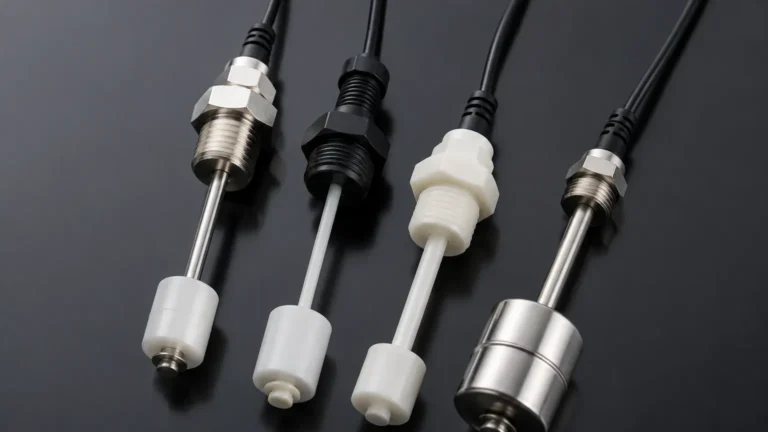
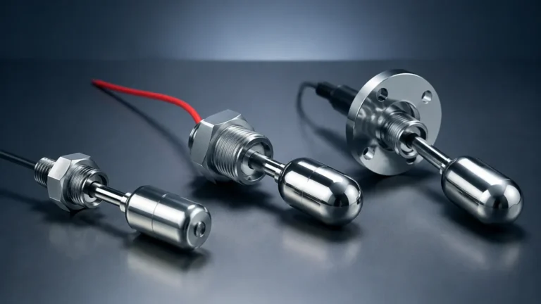
The level switch a 01 041 operates on the principle of magnetic buoyancy. This technology is favored in B2B industrial applications due to its simplicity, low power consumption, and long-term stability. The assembly typically consists of three primary components: a hollow float containing a permanent magnet, a stationary stem containing a hermetically sealed reed switch, and a mounting fitting.
The Reed Switch Mechanism
Inside the stationary stem, one or more reed switches are positioned at specific set points. A reed switch consists of two overlapping, ferromagnetic blades (reeds) sealed within a glass envelope. In its default state, the blades are separated. As the liquid level rises, the buoyant float moves along the stem. When the float’s internal magnet reaches the position of the reed switch, the magnetic field pulls the two blades together, closing the electrical circuit. When the level drops, the magnet moves away, and the mechanical tension in the blades causes them to reset to the open position.
Advantages of the Magnetic Design
Because the electrical components (the reed switches) are hermetically sealed inside the stem, they are protected from oxidation, moisture, and the process media itself. This isolation ensures that the level switch a 01 041 can operate in harsh environments where exposed electrodes would fail due to corrosion or coating. Furthermore, because the switching action is triggered by a magnetic field rather than mechanical linkage, there is minimal wear on the internal components, leading to a service life often exceeding millions of cycles.
Technical Specifications and Selection Criteria
When evaluating a level switch a 01 041 for a specific project, engineers must consider the physical and chemical properties of the media, as well as the electrical requirements of the control system. The following table provides a comparison of common level switch technologies to help contextualize where magnetic float switches are most effective.
Technology Comparison Table
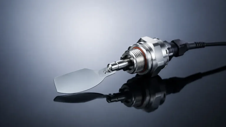
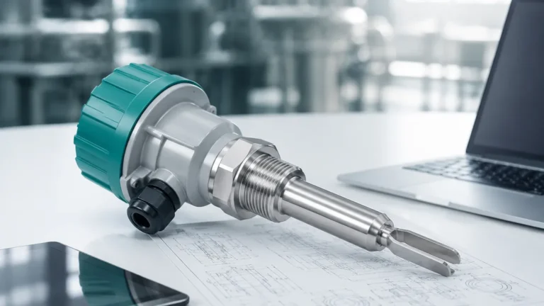
| Feature | Magnetic Float (a 01 041 Type) | Tuning Fork (Vibrating) | Ultrasonic Switch | Capacitive Switch |
| :— | :— | :— | :— | :— |
| Best Use Case | Clean liquids, oils, water | Slurries, powders, liquids | Non-contact, corrosive | High-temp, sticky media |
| Viscosity Limit | Low to Medium (< 500 cSt) | High (< 10,000 cSt) | Low | Medium |
| Moving Parts | Yes (Float) | No (Vibrating tines) | No | No |
| Power Required | None (Passive) | Yes (Active) | Yes (Active) | Yes (Active) |
| Cost | Low to Moderate | Moderate to High | High | Moderate |
| Maintenance | Periodic cleaning of float | Minimal | Low | High if coating occurs |
Material Compatibility
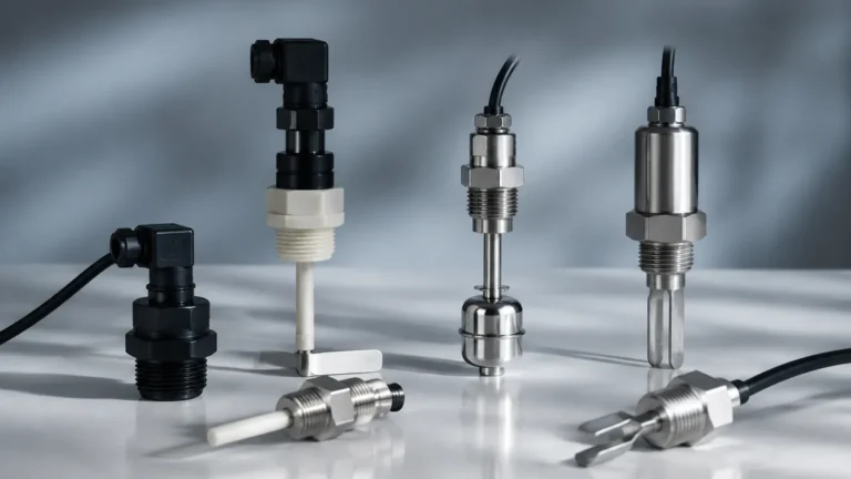
The level switch a 01 041 is often manufactured using materials such as Stainless Steel (316L), Polypropylene (PP), or Polyvinylidene Fluoride (PVDF).
- Stainless Steel: Ideal for high-pressure applications (up to 30 bar or 3.0 MPa) and high temperatures (up to 120°C or 248°F). It is the standard choice for the food and beverage industry and oil-based hydraulic systems.
- Polypropylene: A cost-effective solution for water treatment and diluted acidic or alkaline solutions, generally limited to lower temperatures (up to 80°C) and pressures (up to 5 bar).
- PVDF: Reserved for highly aggressive chemical environments where standard plastics or metals would degrade.
Installation Considerations and Best Practices
Proper installation is paramount to ensuring the longevity of the level switch a 01 041. While these devices are robust, they are sensitive to certain environmental factors that can lead to false triggering or mechanical failure.
Mounting Orientation
Most switches of this type are designed for vertical installation through the top or bottom of a tank. However, horizontal side-mount versions are available for applications where vertical space is restricted. For the level switch a 01 041, it is essential to ensure the stem is perfectly vertical (within ±30 degrees) to prevent the float from binding against the stem due to friction.
Managing Turbulence and Agitation
In tanks where mixers or high-velocity return lines create turbulence, the float may bounce, leading to "chatter" in the electrical signal. To mitigate this, engineers should:
1. Use a Stilling Well: A perforated pipe (typically 50mm to 100mm in diameter) installed around the switch to dampen wave action.
2. Software Buffering: Implement a time-delay (e.g., 2–5 seconds) in the PLC (Programmable Logic Controller) logic to ignore momentary state changes caused by splashing.
3. Relay Protection: Never connect the level switch a 01 041 directly to a high-current load like a pump motor. Always use an intermediate power relay or contactor. The reed switches inside these units are typically rated for low currents (e.g., 0.5A to 1.0A at 24V DC).
Avoiding Magnetic Interference
Since the switch relies on a magnetic field, it should be kept away from large motors, transformers, or ferrous metal walls that could distort the magnetic flux. A minimum clearance of 50mm from ferrous tank walls is generally recommended.

Limitations and Prohibitions
While the level switch a 01 041 is a versatile tool, it is not a universal solution. Engineers must be aware of the following limitations:
- Solid Contamination: If the liquid contains magnetic particles (iron filings) or heavy sediment, these can accumulate on the float magnet or jam the float's movement. In such cases, a non-contact ultrasonic or radar sensor is preferred.
- Coating and Scaling: In applications like wastewater or lime slurry, calcium deposits or biological growth can weigh down the float, causing it to sink and fail to trigger.
- Interface Detection: Standard float switches are calibrated for a specific specific gravity (typically > 0.7). If used in a dual-liquid interface (e.g., oil on water), the float must be specifically weighted to sink in the top layer but float on the bottom layer.
Maintenance and Troubleshooting
Routine maintenance for the level switch a 01 041 involves a visual inspection of the float's mobility. In systems with scale-forming liquids, the float should be removed and cleaned with a mild solvent or descaling agent annually.
Common Troubleshooting Steps:
- Switch remains closed: Check for a stuck float or a welded reed switch caused by an electrical surge. Verify that the load does not exceed the contact rating.
- Switch remains open: Check for a punctured float (which has filled with liquid and sunk) or broken internal wiring.
- Intermittent signals: Often caused by loose wiring terminals or excessive vibration in the tank structure.
Frequently Asked Questions (FAQ)
Q: Can the level switch a 01 041 be used in explosive atmospheres?
A: Only if it is certified as "Intrinsically Safe" (Ex i) and used in conjunction with a certified safety barrier. Passive reed switches do not generate heat, but the electrical energy in the circuit must be limited to prevent sparks.
Q: How do I change the switch logic from Normally Open (NO) to Normally Closed (NC)?
A: On many magnetic float models, this is achieved by removing the retaining clip at the end of the stem, flipping the float 180 degrees, and reinstalling it. This reverses the position of the magnet relative to the switch.
Q: What is the maximum pressure the level switch a 01 041 can withstand?
A: This depends entirely on the material. Stainless steel variants can typically handle 30 bar (435 psi), while plastic versions are usually rated for 5 bar (72 psi) or less.
Q: Is it possible to have multiple switch points on a single stem?
A: Yes, custom configurations allow for multiple reed switches to be placed at different heights, allowing for Low, High, and Overfill detection within a single tank penetration.
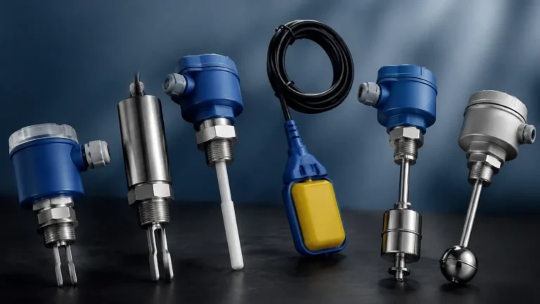
For engineers seeking reliable point-level detection, the level switch a 01 041 offers a proven balance of simplicity and durability. By carefully matching the material properties to the process media and following standardized installation protocols, these switches provide an essential layer of safety and automation for modern industrial fluid systems. For more complex requirements, exploring the full range of Level Switches ensures that the specific demands of pressure, temperature, and chemical compatibility are met with precision.