Switch Level 1 2 3
Switch Level 1 2 3
In industrial process automation, point level detection serves as the primary safeguard for vessel management. The concept of "switch level 1 2 3" refers to the strategic implementation of multiple detection points—typically Low (Level 1), High (Level 2), and High-High or Overflow (Level 3)—to ensure operational continuity and safety. Unlike continuous level measurement, which provides a constant data stream of the tank's contents, level switches provide discrete signals at specific heights to trigger alarms, start or stop pumps, and activate emergency shutdown systems.
Selecting the appropriate configuration for these three critical levels requires an understanding of the underlying physics of level detection and the specific demands of the medium being measured. This guide examines the principles, selection criteria, and installation best practices for multi-point level switch systems.
Measurement Principles of Level Switches
Before determining the placement for switch level 1 2 3, engineers must select a sensing technology compatible with the physical properties of the process material. Each technology operates on a distinct physical principle.
Float and Displacement Switches
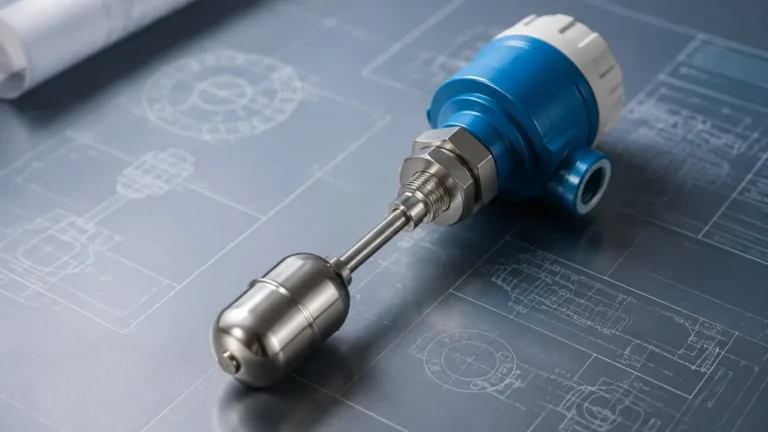
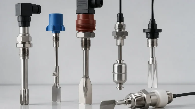
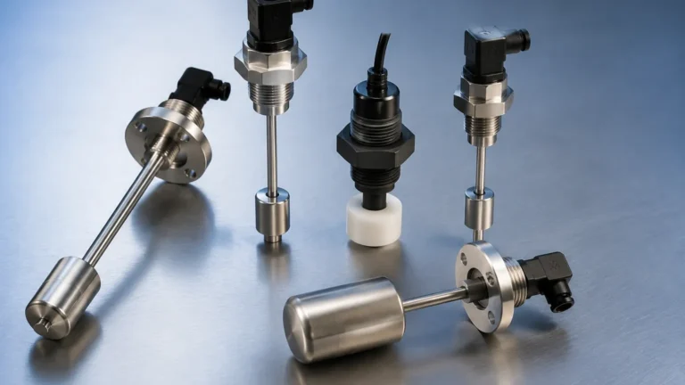
Float switches operate on the principle of buoyancy. A float, designed with a lower density than the process liquid, moves vertically with the liquid level. As the float reaches a predetermined point, it mechanically or magnetically actuates a microswitch or a reed switch. These are highly reliable for clean liquids but are susceptible to fouling in viscous or scaling media.
Vibrating Point Level Switches (Tuning Fork)
Commonly used for both liquids and solids, vibrating switches utilize a sensing element (the fork) that is piezoelectrically vibrated at its natural frequency. When the medium covers the fork, the frequency changes or the vibration is damped. The internal electronics detect this shift and switch the output state. These are favored for their immunity to turbulence, bubbles, and foam.
Capacitive Level Switches
Capacitance sensors detect the change in electrical capacitance between the probe and the tank wall (or a reference electrode). As the medium displaces air around the probe, the dielectric constant changes, altering the capacitance. This technology is versatile but requires calibration for different media and can be affected by material buildup on the probe.
Ultrasonic Point Switches
Ultrasonic switches use a pair of crystals (transmitter and receiver) separated by a small gap. When the gap is filled with liquid, the ultrasonic signal is transmitted across the gap; when the gap is filled with air or gas, the signal is attenuated. This non-contact or gap-contact method is ideal for chemically aggressive fluids.
Understanding the Switch Level 1 2 3 Hierarchy
In a standard three-point control logic, each level represents a specific functional threshold within the vessel. Implementing Level Switches across these three points creates a redundant and automated safety loop.
Level 1: Low Level (L / LL)
Level 1 is typically positioned at the bottom of the tank, just above the outlet nozzle. Its primary function is "Dry Run Protection."
- Action: If the level drops below this point, the switch signals the control system to stop discharge pumps or close outlet valves.
- Risk Mitigated: Prevents pump cavitation and mechanical damage caused by running dry.
Level 2: High Level (H)
Level 2 is the operational "Full" setpoint. It is positioned at the desired maximum working volume of the tank.
- Action: When the medium reaches this switch, it triggers the closure of the inlet valve or stops the fill pump.
- Risk Mitigated: Prevents standard overfilling and ensures the process stays within design parameters.
Level 3: Extra-High / Overflow (HH)
Level 3 is the safety interlock point, positioned above Level 2. It acts as an emergency backup.
- Action: If Level 2 fails to stop the filling process, Level 3 activates an independent emergency shutdown (ESD) and local/remote alarms.
- Risk Mitigated: Prevents catastrophic tank overflow, environmental contamination, and hazardous spills.
Selection Criteria for Multi-Point Systems
Choosing the right hardware for switch level 1 2 3 depends on several environmental and chemical factors. The following table provides a general selection framework for common industrial scenarios.
| Application Factor | Float Switch | Vibrating Fork | Capacitive | Ultrasonic Gap |
| :— | :— | :— | :— | :— |
| Media Type | Clean Liquids | Liquids/Granules | Liquids/Slurries | Clear Liquids |
| Viscosity | Low (< 500 cP) | Medium (< 10,000 cP) | High | Low |
| Pressure Range | Up to 40 bar | Up to 64 bar | Up to 100 bar | Up to 20 bar |
| Temperature | -40 to 150°C | -50 to 250°C | -50 to 200°C | -40 to 130°C |
| Buildup Risk | High | Low | Moderate | Low |
| Moving Parts | Yes | No | No | No |
Installation and Engineering Considerations
Correct physical installation is as vital as technology selection. Even the most accurate switch will fail if placed in a turbulent or obstructed zone.
1. Nozzle Length and Diameter: For vibrating forks and capacitive probes, ensure the nozzle is not so long that material can become trapped, creating a "false full" reading. The active sensing element must extend fully into the vessel.
2. Avoid Turbulence: Do not install switches directly in the path of the inlet flow. The kinetic energy of the incoming fluid can cause mechanical damage or cause the switch to oscillate between states. If placement near an inlet is unavoidable, use a baffle plate or a stilling well.
3. Orientation: While many switches can be mounted horizontally or vertically, horizontal mounting is preferred for point level detection to minimize the "dead zone" and ensure the switch triggers at the exact height intended.
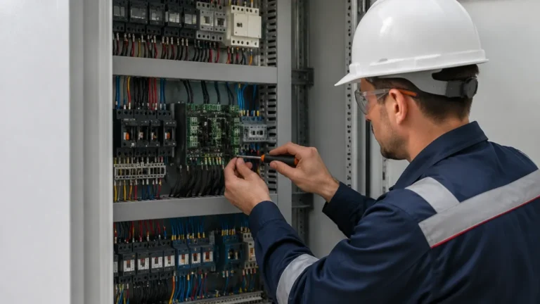
4. Wiring and Logic: For safety-critical Level 3 applications, the switch should be wired in a "Normally Closed" (NC) configuration. In this setup, a loss of power or a broken wire is interpreted by the controller as a high-level alarm, ensuring the system fails to a safe state.

Limitations of Point Level Switches
While robust, switch level 1 2 3 configurations have inherent limitations:
- Discrete Data Only: They cannot tell you how much material is between Level 1 and Level 2. If inventory management is required, a radar or ultrasonic transmitter should be used in conjunction with the switches.
- Coating and Scaling: In applications like wastewater or lime slurry, material can build up on the sensor. While tuning forks are somewhat self-cleaning, significant scaling will eventually cause a malfunction.
- Mechanical Wear: Float switches involve moving parts that can wear out over time or become stuck due to crystallization or debris.
Frequently Asked Questions (FAQ)
Q: Can I use one probe for all three levels?
A: Yes, certain technologies like multi-point float switches or conductive probes allow for multiple switching points on a single stem. However, for high-safety applications (Level 3), it is often recommended to use a physically independent switch to ensure redundancy.
Q: What is the difference between a level switch and a level transmitter?
A: A level switch provides a binary output (On/Off) at a specific point. A level transmitter provides a continuous signal (e.g., 4-20mA or Modbus) representing the exact level across the entire height of the tank.
Q: How often should switch level 1 2 3 systems be tested?
A: This depends on the criticality of the process. For safety-instrumented systems (SIS), a proof test interval is usually defined (e.g., every 6 to 12 months) where the level is manually raised, or the switch is removed and tested to ensure it trips the correct logic.
Q: Are these switches suitable for hazardous areas?
A: Yes, but you must specify Explosion-Proof (Ex d) or Intrinsically Safe (Ex i) versions depending on the zone classification (Zone 0, 1, or 2). Always check the ATEX or IECEx certification of the device.
Conclusion
Implementing a robust switch level 1 2 3 strategy is a fundamental requirement for modern industrial safety and efficiency. By understanding the measurement principles of different technologies and adhering to strict installation guidelines, plant operators can prevent equipment damage, avoid environmental incidents, and maintain precise control over their liquid and solid assets. For complex applications involving high pressure, extreme temperatures, or corrosive media, consulting with a specialized manufacturer ensures that the selected instrumentation meets the specific demands of the process environment.