Level 1 Controls
Level 1 Controls
In the architecture of industrial automation, specifically within the framework of the Purdue Model (ISA-95), Level 1 controls represent the fundamental field layer where physical processes are sensed and manipulated. For process engineers and plant managers, Level 1 controls in fluid and bulk solid management refer to the hardware—sensors, actuators, and local controllers—that interact directly with the medium. This layer is the critical interface between the physical world and the digital supervisory systems. Without robust Level 1 sensing, higher-level optimization and data analytics remain disconnected from reality.
In level measurement applications, Level 1 controls primarily consist of point-level detection devices and continuous measurement transmitters. Among these, Level Switches serve as the primary safety and operational threshold markers, ensuring that tanks do not overflow and pumps do not run dry. Understanding the principles, selection criteria, and installation nuances of these devices is essential for maintaining process integrity.
Measurement Principles of Level 1 Hardware
Level 1 control devices operate on various physical principles to detect the presence or height of a medium. Selecting the correct principle depends on the physical properties of the substance being measured, such as density, dielectric constant, conductivity, and viscosity.
1. Vibrating Fork (Tuning Fork) Principle
This technology utilizes a sensing element shaped like a tuning fork, which is vibrated at its resonant frequency by internal piezoelectric crystals. When the fork is immersed in a liquid or solid, the frequency of vibration changes or is dampened. The internal electronics detect this frequency shift and trigger a switching output. This principle is highly resistant to changes in flow, turbulence, bubbles, and foam, making it a versatile choice for Level 1 safety loops.
2. Float and Displacement Principle
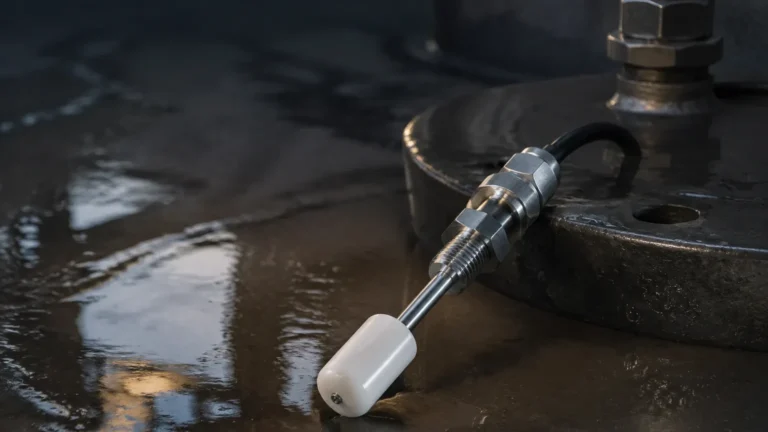
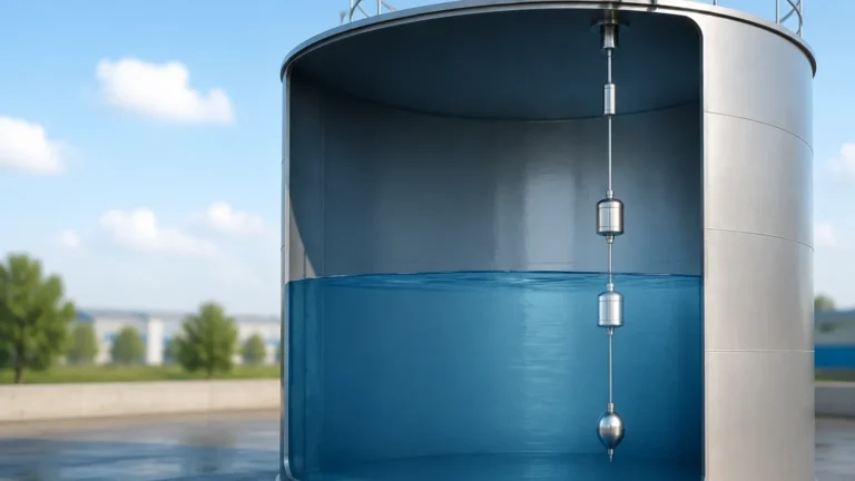
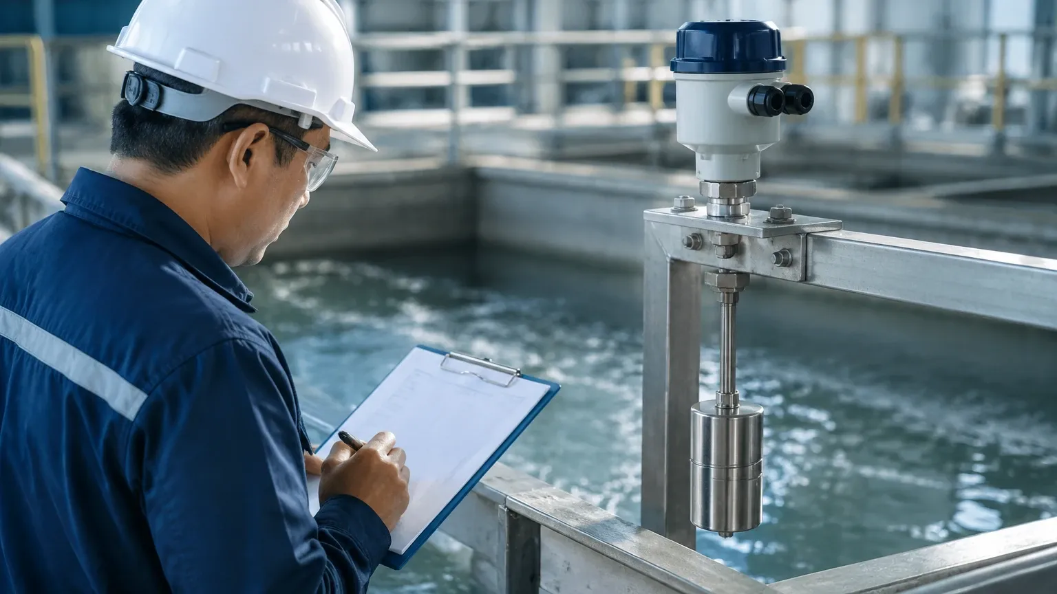
Float-based controls rely on Archimedes' principle of buoyancy. A float, typically containing a magnet, moves vertically with the liquid level. As the float reaches a predetermined point, the magnetic field actuates a reed switch or a microswitch. Displacement-based systems, conversely, measure the change in apparent weight of a submerged body as the liquid level rises. These are purely mechanical or electromechanical and are often favored for their simplicity in non-coating applications.
3. Capacitive Sensing
Capacitive level controls treat the sensor probe and the tank wall (or a second probe) as two plates of a capacitor. The medium acts as the dielectric material. As the level rises, the total capacitance of the system changes because the dielectric constant of the medium is different from that of air. This change is converted into a switching signal or a continuous value. This principle is effective for both liquids and solids but requires calibration based on the specific dielectric properties of the material.
4. Conductive Principle
Used exclusively for conductive liquids (such as water or acids), this method employs electrodes. When the liquid touches the electrode, it completes an electrical circuit between the probe and the tank wall (or a reference probe). The low-voltage current flow is detected by a controller to trigger a Level 1 response. This is often the most cost-effective solution for simple high/low-level alarms in water treatment.
Key Evaluation Criteria for Level 1 Control Systems
When designing Level 1 controls, engineers must evaluate several technical parameters to ensure long-term reliability and compatibility with Level 2 (PLC/DCS) systems.
* Media Compatibility: The wetted materials (e.g., 316L stainless steel, PTFE, PP) must be chemically resistant to the process medium. For corrosive chemical applications, plastic-coated probes are often necessary.
* Process Conditions: Standard Level 1 devices are rated for specific temperature and pressure ranges. High-pressure boilers or cryogenic storage require specialized seals and thermal offsets to protect the electronics.
* Output Type: Level 1 controls must communicate with the control room. Common outputs include SPDT/DPDT relays, PNP/NPN transistors, or 4-20 mA loops with HART protocol. For safety-instrumented systems (SIS), SIL-rated devices are mandatory.
* Response Time: In fast-filling tanks, the latency of the sensor can lead to overshoots. Vibrating forks typically offer faster response times (milliseconds) compared to thermal dispersion or mechanical float switches.
* Hysteresis and Repeatability: Repeatability ensures the switch triggers at the exact same point every time, while adjustable hysteresis prevents "chattering" (rapid cycling) when the liquid surface is turbulent.
Technology Selection Table
The following table provides a comparison of common technologies used in Level 1 control applications to assist in the selection process.
| Technology | Suitable Media | Advantages | Limitations |
| :— | :— | :— | :— |
| Vibrating Fork | Liquids, Powders, Granules | No calibration needed; ignores foam and bubbles. | Subject to material build-up between forks. |
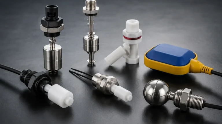
| Float Switch | Clean Liquids | Simple, low cost, no power required (passive). | Moving parts can jam; sensitive to turbulence. |
| Capacitive | Liquids, Solids, Slurries | No moving parts; can detect interfaces. | Requires calibration; sensitive to dielectric changes. |
| Conductive | Conductive Liquids | Very economical; compact design. | Only works with conductive media; probe fouling. |
| Ultrasonic (Point) | Liquids | Non-contact; high accuracy. | Affected by heavy vapors, foam, and high pressure. |
| Radar (Point) | Liquids, Solids | Highly accurate; unaffected by dust/vapor. | Higher initial investment cost. |
Installation Considerations and Best Practices
Proper installation is the most significant factor in the reliability of Level 1 controls. Even the most advanced sensor will fail if placed in an environment that interferes with its operating principle.
Mounting Position
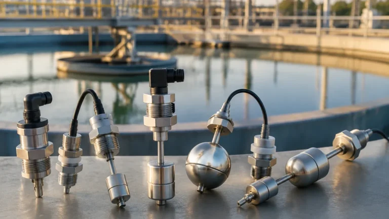
Level switches can be mounted horizontally (side-wall) or vertically (top-down). Vertical mounting is preferred for high-level alarms to ensure the sensor is out of the way of filling streams. Horizontal mounting is common for low-level pump protection. When mounting side-wall switches, ensure the probe is angled slightly downward (if the technology allows) to facilitate drainage and prevent material accumulation.
Avoiding Interference
* Inlet Streams: Never install a level sensor directly in the path of an incoming fluid stream. The force of the fluid can damage mechanical floats or cause false triggers in electronic sensors.
* Agitators and Baffles: Ensure there is sufficient clearance between the sensor and moving parts like agitator blades. In tanks with heavy agitation, a stilling well (a pipe surrounding the sensor) may be required to provide a calm surface for measurement.
* Nozzle Length: For ultrasonic or radar-based Level 1 controls, the mounting nozzle should be as short as possible. Long nozzles can create "ringing" or false echoes that interfere with the signal near the top of the tank.
Electrical Guarding
In industrial environments, electromagnetic interference (EMI) from large motors or variable frequency drives (VFDs) can induce noise in sensor cables. Use shielded cables and ensure that the Level 1 hardware is properly grounded to the vessel or a dedicated instrument ground.
Limitations and Risks in Level 1 Operations
While Level 1 controls are designed for robustness, they are not infallible. Awareness of their limitations prevents process failures.
1. Build-up and Coating: In many chemical and wastewater applications, media can stick to the sensor probe. Over time, this coating can simulate the presence of the liquid, leading to a permanent "high level" signal. In these cases, technologies with "active shield" or coating rejection (like specific capacitive or vibrating fork models) should be used.
2. Density Fluctuations: Mechanical float switches are calibrated for a specific specific gravity (SG). If the process fluid changes (e.g., switching from oil to water), the float may no longer trigger at the correct level or may fail to float entirely.
3. Mechanical Wear: Any device with moving parts, such as float switches or rotating paddles, has a finite mechanical life. These components are prone to fatigue and jamming due to sediment or crystallization.
4. Environmental Factors: Extreme ambient temperatures can cause electronics to drift. In outdoor installations, sunshields and insulated housings are often necessary to maintain the accuracy of Level 1 controls.
Frequently Asked Questions (FAQs)
Q: What is the difference between Level 1 and Level 2 controls?
A: Level 1 refers to the field devices (sensors and actuators) that perform the actual measurement and physical action. Level 2 refers to the supervisory control layer, such as a PLC or SCADA system, which receives data from Level 1 and executes complex logic or provides a user interface.
Q: Can a Level 1 switch be used for continuous measurement?
A: No. A switch provides a binary signal (on/off) at a specific point. For continuous tracking (e.g., 0% to 100% volume), a level transmitter is required. However, multiple switches can be used together to provide stepped level control (e.g., 25%, 50%, 75%).
Q: How often should Level 1 controls be calibrated?
A: This depends on the technology and the criticality of the application. Mechanical switches rarely need calibration but require frequent functional testing (proof testing). Capacitive and ultrasonic sensors should be checked annually or whenever there is a significant change in the process medium.
Q: What is a "fail-safe" configuration in Level 1 controls?
A: Fail-safe refers to the state the switch enters upon loss of power. For high-level alarms, the switch should be configured so that a loss of power mimics a high-level condition (normally closed), triggering a shutdown to prevent overflow.
Q: Are Level 1 controls suitable for hazardous areas?
A: Yes, but they must be appropriately rated. This usually involves using intrinsically safe (IS) barriers or explosion-proof (Ex d) housings, depending on the zone classification of the environment.
By carefully integrating reliable Level 1 controls into the process architecture, industrial facilities can achieve higher safety standards and more efficient automation. Whether using simple conductive probes or advanced vibrating forks, the fundamental goal remains the same: providing accurate, real-time data to the heart of the control system.