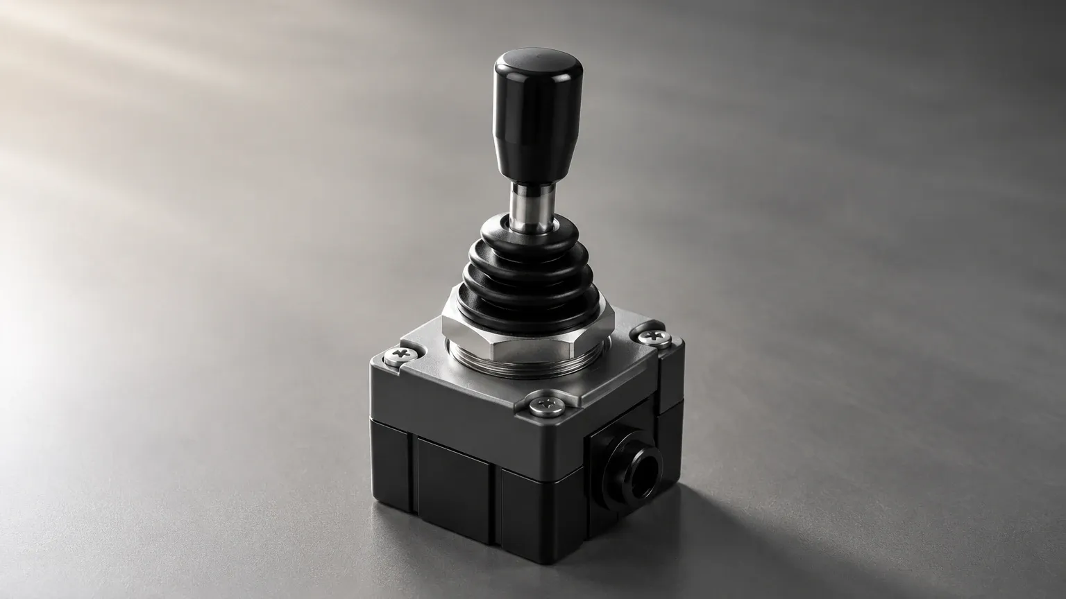
4 Position Lever Switch
4 Position Lever Switch
In the field of industrial automation and fluid management, the precise control of liquid levels is fundamental to operational safety and process efficiency. While many level measurement tasks require continuous monitoring, many critical applications rely on point-level detection to trigger alarms, start or stop pumps, and prevent tank overfills. Among the various mechanical configurations available, the lever-operated switch remains a robust and reliable choice. Specifically, the concept of a 4 position lever switch—often utilized in complex control logic or multi-stage tank monitoring—provides a versatile solution for managing multiple setpoints within a single mechanical assembly.
Understanding how these Level Switches operate, their selection criteria, and their installation requirements is essential for engineers and plant operators aiming to optimize their level control systems.
Principles of Lever-Operated Level Measurement
Before diving into the specifics of multi-position configurations, it is necessary to understand the underlying physical principles that govern lever-type level switches. These devices primarily operate based on the principle of buoyancy and mechanical advantage.
The Buoyancy Principle
At the heart of the switch is a float, which is designed to be less dense than the liquid it is monitoring. According to Archimedes' principle, the float experiences an upward force equal to the weight of the liquid it displaces. In a lever-style switch, this float is attached to a rigid arm or lever, which is pivoted at a fixed point (the fulcrum).
Mechanical Actuation
As the liquid level rises or falls, the float moves vertically, causing the lever arm to rotate around its pivot. This rotational movement is then used to actuate an electrical switching element. In industrial environments, this actuation is typically achieved through one of two methods:
1. Direct Mechanical Linkage: The lever physically pushes a micro-switch plunger or toggles a mechanical contact.
2. Magnetic Coupling: The lever arm contains a permanent magnet. As the arm moves, the magnetic field passes through a non-magnetic housing (usually stainless steel or plastic) to actuate a reed switch or a dry contact on the dry side of the instrument. This method is preferred for high-pressure or hazardous applications as it eliminates the need for dynamic seals that could leak.
Defining the 4 Position Configuration
In standard applications, a level switch might only have two states: "on" or "off." However, a 4 position lever switch refers to a specialized control component or a multi-point level assembly capable of identifying four distinct states or levels. This can be achieved through a single lever with multiple internal contact stages or, more commonly in heavy industry, a series of lever-actuated switches integrated into a single control panel to manage four specific process conditions (e.g., Low-Low, Low, High, and High-High levels).
Key Evaluation Criteria for Selection
Selecting the correct level switch requires a thorough analysis of the process environment. A 4 position lever switch must be matched to the chemical, thermal, and physical properties of the medium.
1. Material Compatibility
The wetted parts—the float, the lever arm, and the process connection—must be resistant to corrosion. Common materials include:
* Stainless Steel (316L): The standard for oil, gas, and high-temperature water applications. It offers excellent durability and resistance to oxidation.
* Polypropylene (PP): Frequently used in water treatment and acidic environments where metallic components might corrode.
* PTFE/Teflon: Reserved for highly aggressive chemical processing where universal chemical resistance is required.
2. Specific Gravity
The float must be sized according to the specific gravity (SG) of the liquid. If the liquid is too light (e.g., certain hydrocarbons with an SG of 0.6), a standard float designed for water (SG 1.0) will not provide enough buoyant force to actuate the lever mechanism. Engineers must confirm that the float's displacement volume is sufficient to overcome the mechanical resistance of the switch contacts.
3. Pressure and Temperature Ratings
Industrial tanks often operate under significant pressure. A 4 position lever switch used in a boiler or a pressurized chemical reactor must have a float capable of withstanding the external pressure without collapsing. Standard industrial models are often rated for pressures up to 40 bar (approx. 580 psi) and temperatures exceeding 200°C (392°F).
4. Electrical Specifications
The switching capacity must match the control system. Most level switches utilize SPDT (Single Pole Double Throw) or DPDT (Double Pole Double Throw) contacts. It is vital to ensure the voltage (AC or DC) and amperage ratings are compatible with the pumps or PLCs (Programmable Logic Controllers) they are intended to drive.
Selection Table: Lever Switch Comparison
| Feature | Standard Magnetic Lever | Heavy-Duty Mechanical | Multi-Point Lever Assembly |
| :— | :— | :— | :— |
| Primary Use | General liquid level | High-viscosity fluids | Multi-stage pump control |
| Max Pressure | 25 bar (362 psi) | 40 bar (580 psi) | 10 bar (145 psi) |
| Max Temp | 150°C (302°F) | 250°C (482°F) | 80°C (176°F) |
| Switching Points | 1 to 2 | 1 | Up to 4 |
| Material | SS316 / PVC | SS316 / Monel | PP / PVDF |
Installation Considerations
Correct installation is paramount to ensuring the longevity and accuracy of a 4 position lever switch. Because these devices rely on mechanical movement, physical obstructions can lead to failure.
Orientation and Clearance
Lever switches are typically side-mounted through a flange or a threaded NPT/G connection. It is critical to ensure there is enough internal clearance for the lever arm to travel through its full arc. If the tank has internal baffles, heating coils, or agitators, the switch must be positioned to avoid physical interference.
Turbulence and Stillwells
In tanks with high turbulence—such as those with high-speed mixers or rapid inflow—the float may bounce, leading to "chatter" in the electrical contacts. This can damage pumps or cause false alarms. In such cases, installing the lever switch within a stillwell (a vertical pipe that dampens surface movement) is recommended.
Wiring and Sealing
For 4 position configurations involving multiple contacts, cable management becomes complex. Ensure that the conduit entries are properly sealed with NPT glands to prevent moisture ingress, which is a leading cause of premature switch failure in outdoor or wash-down environments.
Limitations of Lever-Type Switches
While highly reliable, lever-operated level switches are not suitable for every application:
* Coating and Scaling: If the liquid is prone to crystallization or heavy scaling (e.g., lime slurry), the buildup on the pivot point can cause the lever to jam.
* High Viscosity: Extremely thick liquids may impede the movement of the float, leading to delayed response times.
* Mechanical Wear: Because they contain moving parts, lever switches are subject to mechanical fatigue over many thousands of cycles, unlike solid-state ultrasonic or radar sensors.
Practical Application: Multi-Stage Pump Control
A common use case for a 4 position lever switch logic is in a sump pump or reservoir management system. The four positions typically correspond to:
1. Position 1 (Low-Low): Dry run protection. Shuts down all pumps to prevent damage.
2. Position 2 (Low): Stop point for the primary pump during normal operation.
3. Position 3 (High): Start point for the lead pump.
4. Position 4 (High-High): Emergency alarm or start point for a secondary (lag) pump to prevent overflow.
By consolidating these functions into a coordinated lever-switch system, engineers can create a robust, fail-safe control loop that does not rely on complex software for basic safety functions.
Frequently Asked Questions (FAQs)
Q: Can a lever switch be used in hazardous (Ex) areas?
A: Yes, many lever switches are designed for hazardous environments. These typically use explosion-proof housings or are certified as intrinsically safe when used with an appropriate Zener barrier.
Q: How do I test a 4 position lever switch during maintenance?
A: For most mechanical switches, a manual lift test is performed. With the tank empty or the switch removed, the lever is manually moved through its range of motion while a technician confirms the electrical continuity changes at the control panel.
Q: What is the difference between a horizontal and vertical lever switch?
A: A horizontal lever switch is mounted through the side of a tank and moves up and down. A vertical lever (or swing) switch is often mounted from the top, though these are less common than traditional vertical float switches. The "lever" designation almost always implies a side-mount rotational movement.
Q: Can these switches handle liquids with solids?
A: Small amounts of suspended solids are generally acceptable, but large or fibrous debris can entangle the lever arm. In such environments, a non-contact level sensor or a flush-diaphragm pressure transmitter might be more appropriate.
Conclusion
The 4 position lever switch, whether implemented as a single complex component or a strategic array of Level Switches, offers a time-tested solution for multi-point level detection. By understanding the mechanical principles of buoyancy and the specific requirements of the process media—such as specific gravity, temperature, and chemical aggressiveness—engineers can specify a system that provides reliable protection and automation for years of service. When properly installed and maintained, these mechanical systems provide a level of certainty that is essential for high-stakes industrial operations.