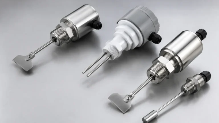
Floatless Level Switch 61f Gp N8
Floatless Level Switch 61f Gp N8
In industrial fluid management, the transition from mechanical float systems to electronic control represents a significant leap in reliability and maintenance efficiency. The floatless level switch 61f gp n8 is a cornerstone of this transition, utilizing the conductive properties of liquids to manage pump operations, tank levels, and overflow alarms. Unlike traditional float switches that rely on moving parts prone to wear, jamming, or corrosion, conductive level controllers offer a solid-state solution suitable for a wide range of conductive media.
This guide provides a technical deep dive into the operating principles, selection criteria, and installation best practices for the 61F-GP-N8, a compact 8-pin plug-in controller widely adopted in water treatment, building automation, and industrial process control.
Understanding the Conductive Measurement Principle
Before selecting a specific controller like the 61F-GP-N8, it is essential to understand the underlying physics of conductive level measurement. This technology is designed specifically for liquids that can conduct electricity.
The Electrode Circuit
A conductive level switch system consists of two primary components: the electronic controller (the 61F-GP-N8 unit) and the electrode probes. The probes are suspended at specific heights within the tank or vessel.
1. Secondary Voltage: The controller applies a low-voltage AC signal (typically 8V AC or 24V AC) across the electrodes. Using AC instead of DC is critical as it prevents electrolysis and subsequent electrode corrosion.
2. Circuit Completion: When the liquid level rises and touches the high-level electrode (often labeled E1), a small current flows through the liquid to the common electrode (E3).
3. Relay Activation: The controller detects this current flow and activates an internal relay. This relay can then start or stop a pump, open a valve, or trigger an alarm.
4. Hysteresis (Differential Control): Most systems use a three-electrode setup (E1, E2, and E3). E1 is the high point, E2 is the low point, and E3 is the common/ground. The controller maintains the relay state until the liquid drops below E2, providing a stable control range that prevents "chattering" (rapid cycling of the pump) caused by surface ripples.
Technical Specifications of the 61F-GP-N8
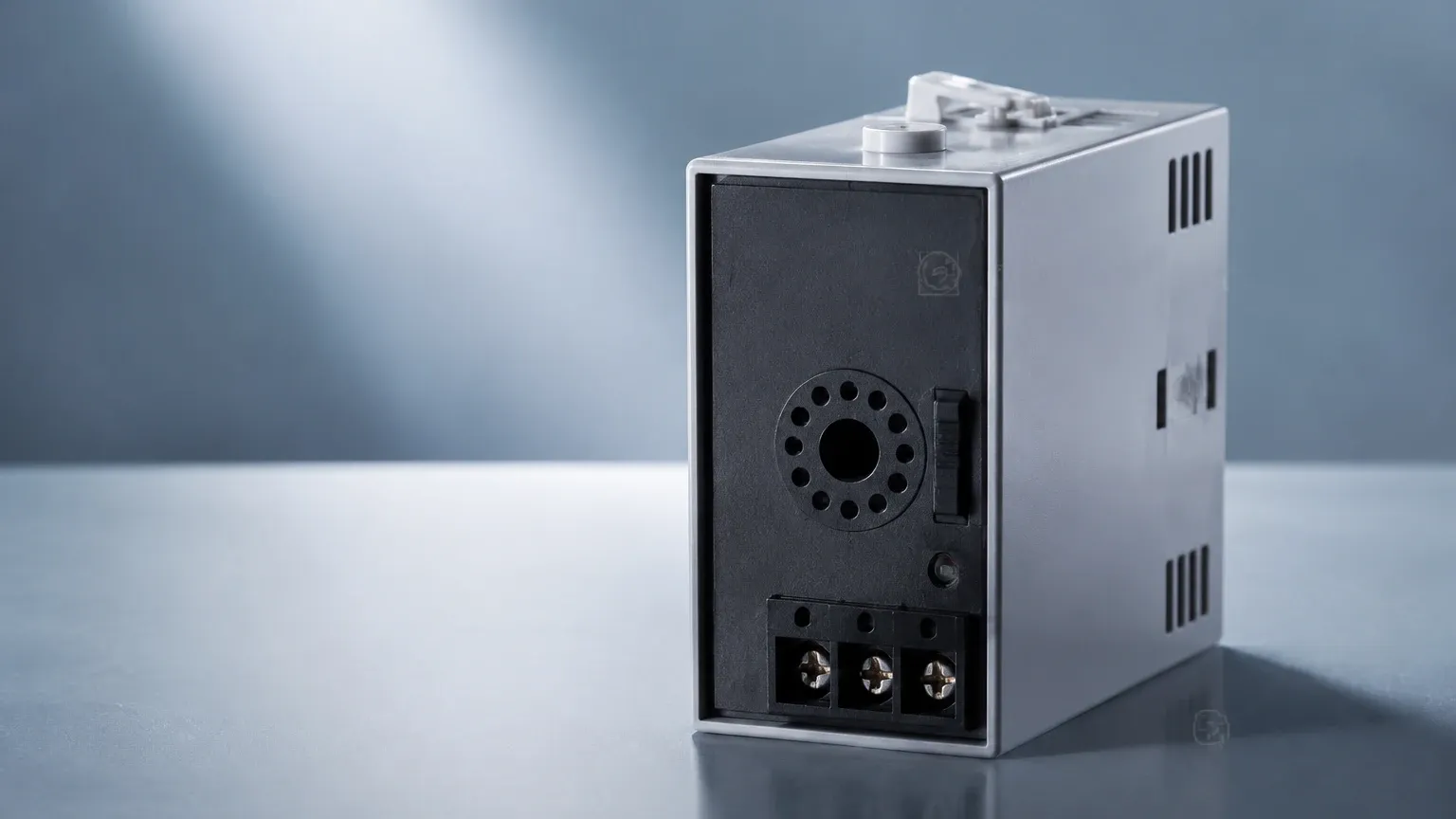
The 61F-GP-N8 is an 8-pin, plug-in version of the standard floatless level controller. Its compact form factor makes it ideal for space-constrained control panels. While various manufacturers produce compatible models, the "61F-GP-N8" designation typically follows a standardized specification set.
Key Performance Parameters
* Supply Voltage: Commonly available in 100V, 110V, 120V, 200V, 220V, or 240V AC (50/60 Hz).
* Inter-electrode Voltage: 8V AC.
* Power Consumption: Approximately 3.5 VA maximum.
* Response Time: Operate time of 80 ms maximum; release time of 160 ms maximum.
* Control Output: 5A at 250V AC (Resistive load).
* Ambient Temperature: -10°C to 55°C.
* Insulation Resistance: 100 MΩ minimum (at 500V DC).
Sensitivity Variations
Not all conductive liquids have the same resistance. The 61F-GP-N8 series often includes variants to handle different liquid types:
| Type | Inter-electrode Resistance | Application Example |
| :— | :— | :— |
| General Purpose | 0 to approx. 4 kΩ | Tap water, wastewater, well water |
| High Sensitivity | Approx. 15 kΩ to 70 kΩ | Distilled water, condensed water |
| Low Sensitivity | 0 to approx. 0.8 kΩ | Saltwater, high-concentration acids/bases |
| Long Distance | 0 to approx. 1.8 kΩ | Remote tanks (up to 2 km wiring) |
Selection Criteria for Level Switches
Choosing the right Level Switches requires a thorough evaluation of the application environment. While the 61F-GP-N8 is highly versatile, engineers must confirm several factors before implementation.
1. Liquid Conductivity
The 61F-GP-N8 requires a minimum level of conductivity. It is unsuitable for oils, pure alcohols, or ultra-pure deionized water. If the medium is non-conductive, alternative technologies such as ultrasonic sensors or radar level meters should be considered.
2. Vessel Material
In a metal tank, the tank wall itself can sometimes serve as the common electrode (E3). However, in plastic or concrete tanks, a dedicated common electrode must be installed and must reach lower than the lowest control electrode.
3. Mounting and Space
The N8 suffix indicates an 8-pin plug-in base (typically a PF083A or similar socket). This allows for rapid replacement without rewiring the base. If the panel uses DIN rail mounting without sockets, different 61F models may be required.
4. Electrode Length and Material
Electrodes are typically made of Stainless Steel (SUS304 or SUS316). For aggressive chemical environments, titanium or Hastelloy electrodes may be necessary. The length must be calculated based on the required high and low trigger points within the tank.
Installation and Wiring Guidelines
Correct installation is paramount to ensuring the longevity and accuracy of the floatless level switch 61f gp n8.
Wiring Configuration for Automatic Water Supply
In a standard automatic supply application (maintaining a tank level), the wiring usually follows this logic:
* Pins 2 and 7: Connect to the AC power source.
* Pin 4: Connects to the Common Electrode (E3).
* Pin 3: Connects to the Low-Level Electrode (E2).
* Pin 1: Connects to the High-Level Electrode (E1).
* Pins 5, 6, and 8: Provide the relay contact outputs (Normally Open/Normally Closed).
Electrode Installation Considerations
1. Avoid Turbulence: Do not install electrodes near the liquid inlet. Turbulent water can cause false triggering. If turbulence is unavoidable, use a stilling well (a perforated pipe) to shield the electrodes.
2. Electrode Spacing: Ensure at least 10 mm to 20 mm of space between electrodes to prevent debris from bridging the gap and creating a short circuit.
3. Grounding: For reliable operation, especially in large systems, ensure the common electrode (E3) is properly grounded.
4. Cable Selection: Use shielded cables for long-distance runs (over 50 meters) to prevent induced voltage from parallel power lines, which can cause the controller to malfunction.
Practical Applications and Limitations
Common Use Cases
* Building Water Towers: Managing the supply pump to ensure the roof tank remains full without overflowing.
* Wastewater Sumps: Triggering drainage pumps when the effluent reaches a specific height.
* Boiler Feed Water: Monitoring water levels in industrial boilers to prevent dry firing.
* Irrigation Systems: Controlling well pumps based on reservoir levels.
Limitations to Consider
While robust, the 61F-GP-N8 has specific limitations:
* Coating and Scaling: If the liquid leaves a conductive residue or scale on the electrodes, the system may "stick" in the ON position even after the liquid level has dropped. Regular cleaning of the probes is required in such environments.
* Vapor and Foam: Heavy foam can be conductive enough to trigger the switch prematurely. If foaming is a constant issue, a capacitive or ultrasonic level switch may be a better fit.
* Non-Conductive Media: As mentioned, this device will not function with hydrocarbons or non-polar solvents.
Maintenance and Troubleshooting
One of the primary advantages of the 61F-GP-N8 is its ease of troubleshooting. Most units feature an integrated LED indicator that shows the relay status.
Common Issues and Solutions
| Symptom | Potential Cause | Solution |
| :— | :— | :— |
| Pump won't start | Secondary voltage failure or broken electrode wire | Check AC voltage at pins 2 & 7; verify continuity of electrode wires |
| Pump won't stop | Electrode bridging or scaling | Clean electrodes; check for debris caught between probes |
| Rapid relay clicking | Surface turbulence or lack of E2 electrode | Install a stilling well; ensure the 3-electrode configuration is used |
| Intermittent operation | Induced noise in long cable runs | Use shielded cable or a long-distance model controller |
Comparison with Other Technologies
In the broader category of Level Switches, the conductive type occupies a specific niche.
* vs. Float Switches: Conductive switches are more reliable in liquids with debris that might jam a mechanical float. They are also easier to adjust; simply cutting the electrode wire changes the set point.
* vs. Ultrasonic Sensors: Ultrasonic sensors are non-contact and better for corrosive or sticky liquids, but they are significantly more expensive and complex to configure than the 61F-GP-N8.
* vs. Optical Switches: Optical switches are great for point detection in clean liquids but fail quickly in opaque or coating-prone fluids where the 61F-GP-N8 excels.
Frequently Asked Questions (FAQ)
Q: Can I use the 61F-GP-N8 for sewage?
A: Yes, but it is recommended to use electrode holders designed for wastewater (like the PS-4S or PS-5S) and to perform regular maintenance to ensure solids do not bridge the electrodes.
Q: What is the maximum length the electrodes can be?
A: For standard models, the electrodes can be several meters long. However, for very deep wells, you must account for the weight of the rods and use appropriate spacers to prevent them from touching.
Q: Can I cut the electrodes to my desired length?
A: Yes, one of the main benefits of this system is that the stainless steel rods can be cut at the installation site to match the exact tank dimensions.
Q: Is the 61F-GP-N8 safe for drinking water?
A: The controller itself is external to the tank. As long as the electrodes used are food-grade stainless steel (SUS316L) and the holders are non-toxic, the system is perfectly safe for potable water applications.
Conclusion
The floatless level switch 61f gp n8 remains a preferred choice for engineers seeking a cost-effective, reliable, and easy-to-maintain solution for conductive liquid level control. By understanding the electrical requirements of the medium and following precise installation protocols, users can achieve years of trouble-free operation. For applications involving non-conductive liquids or requiring continuous level data, exploring the wider range of industrial Level Switches and transmitters is recommended to find the most suitable technology for the specific process requirements.