J Switch Electrical
J Switch Electrical
In the landscape of industrial automation and process control, the term "j switch electrical" often refers to the electrical configuration, junction integration, and switching logic of point-level sensors. These devices, more broadly known as Level Switches, serve as critical components for overfill protection, pump control, and dry-run prevention. Understanding the electrical interface and the mechanical principles behind these switches is essential for engineers designing reliable liquid or solid management systems.
Level switches are discrete sensors that provide a binary output (on/off) when a material reaches a specific height within a tank, silo, or pipe. Unlike continuous level transmitters that provide a constant stream of data, a level switch is designed to trigger an action—such as sounding an alarm or stopping a motor—at a precise set point.
Principles of Level Switch Operation
Before selecting a specific electrical configuration, it is vital to understand the physical measurement principle that triggers the switch. Different media and environmental conditions require different sensing technologies.
1. Vibrating Tuning Fork Switches
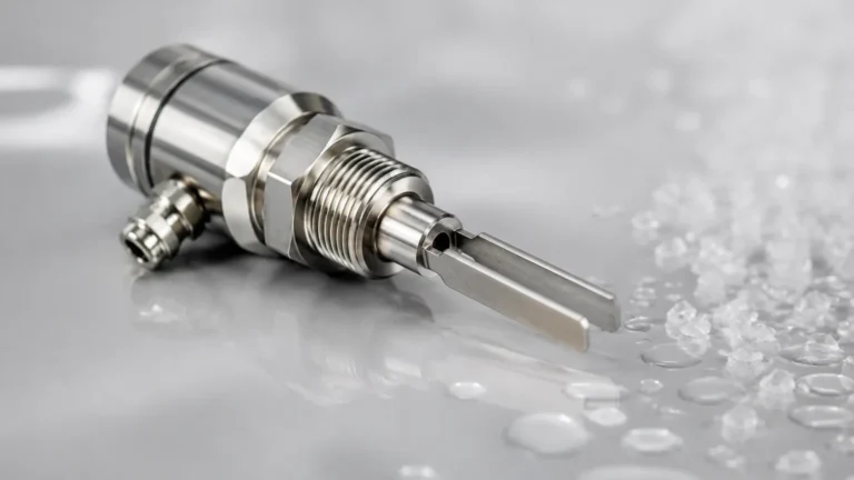
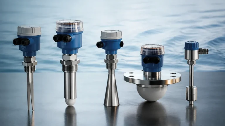
This technology utilizes a fork-shaped element that vibrates at its natural resonant frequency in the air. When the fork is submerged in a liquid or covered by a solid, the frequency changes or the vibration is damped. An internal electronic circuit detects this change and converts it into an electrical signal. Tuning fork switches are highly reliable because they are largely unaffected by flow, bubbles, or turbulence.
2. Float Level Switches
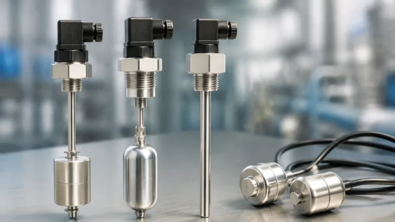
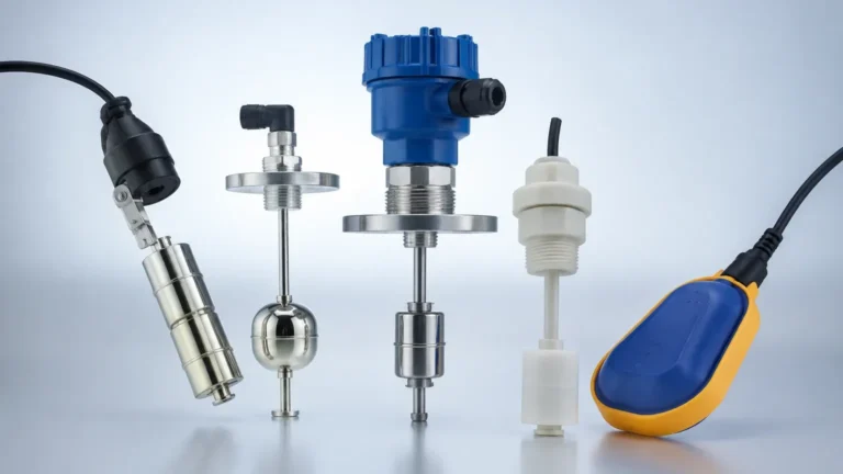
Operating on the principle of buoyancy, a float switch contains a magnet that moves with the liquid level. As the float rises or falls, the magnetic field actuates a reed switch or a microswitch located inside a central stem or housing. These are common in water treatment and simple oil storage applications due to their cost-effectiveness and mechanical simplicity.
3. Capacitance Level Switches
Capacitance switches measure the change in electrical capacitance between a probe and the tank wall (or a reference probe). As the process material displaces air, the dielectric constant changes, altering the capacitance. This technology is excellent for powders, granules, and non-conductive liquids, though it requires calibration based on the material's dielectric properties.
4. Rotary Paddle Switches
Used primarily for bulk solids, a low-speed motor rotates a paddle. When the material reaches the paddle, it creates torque that stalls the motor and flips a mechanical switch. Once the material level drops, a spring returns the motor to its original position.
Electrical Configurations and the "J Switch" Concept
The "j switch electrical" aspect focuses on how the sensor interacts with the wider control circuit. In industrial terminology, the "J" often relates to the junction box (J-box) assembly or the specific "Joint" configuration of the wiring that allows for local manual overrides or integration into a PLC (Programmable Logic Controller).
Contact Types: SPDT vs. DPDT
Most industrial level switches utilize one of two primary contact configurations:
- SPDT (Single Pole Double Throw): This consists of one common terminal, one normally open (NO) terminal, and one normally closed (NC) terminal. It is the standard for most alarm and control functions.
- DPDT (Double Pole Double Throw): This provides two isolated SPDT circuits. This is useful when one switch needs to trigger two separate actions, such as turning on a warning light while simultaneously cutting power to a pump.
Output Logic: NPN vs. PNP
In solid-state switches (like ultrasonic or tuning fork variants), the electrical output is often DC-based.
- NPN (Sinking): The switch connects the load to the negative terminal (ground).
- PNP (Sourcing): The switch connects the load to the positive terminal (V+).
Engineers must match the switch logic to the input requirements of their PLC to ensure signal compatibility.
Technical Selection Criteria
Selecting the correct level switch involves balancing the physical properties of the media with the electrical requirements of the installation site. Use the following table as a general reference for common technologies.
| Technology | Typical Media | Temp. Range | Pressure Range | Electrical Output |
| :— | :— | :— | :— | :— |
| Tuning Fork | Liquids / Fine Solids | -50°C to 150°C | Up to 64 bar | Relay, PNP, Two-wire |
| Float | Clean Liquids | -20°C to 120°C | Up to 20 bar | Reed Switch, SPDT |
| Capacitance | Powders / Corrosives | -40°C to 200°C | Up to 25 bar | Relay, 4-20mA (Switch) |
| Rotary Paddle | Bulk Solids / Grains | -20°C to 80°C | Atmospheric | Microswitch |
Material Compatibility
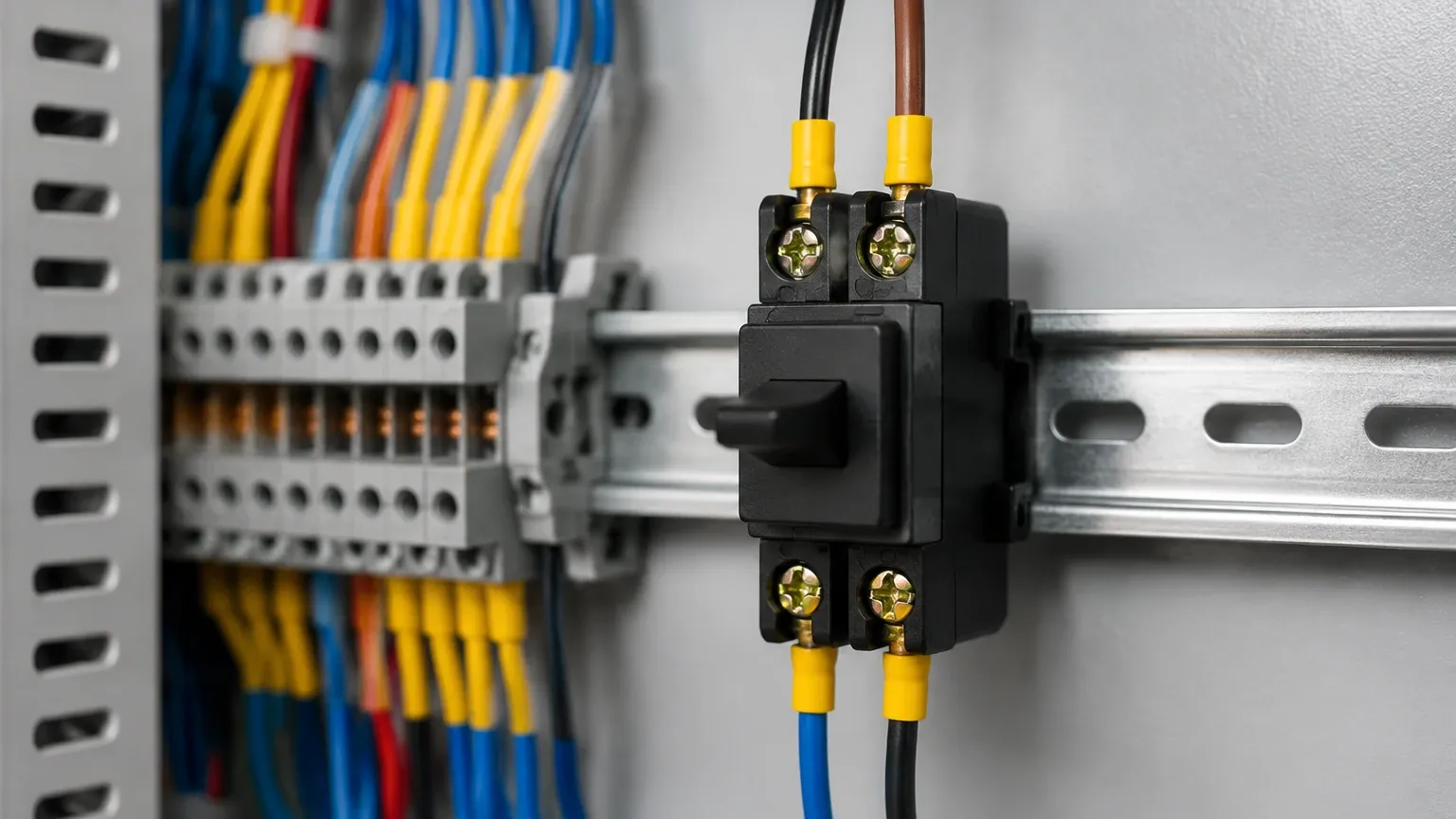
The wetted parts of the switch must be chemically compatible with the process media. Stainless steel (316L) is the industry standard, but for highly corrosive acids, PTFE (Teflon) or PVDF coatings are required. In the context of j switch electrical setups, the housing (junction box) should also be rated for the environment, typically using aluminum or reinforced plastic with IP65 to IP68 ingress protection.
Installation and Wiring Best Practices
Proper installation is the most significant factor in the longevity of a level switch. When dealing with electrical junctions, several engineering standards should be followed.
1. Cable Entry and Sealing
Always use appropriate cable glands to maintain the IP rating of the switch housing. If the switch is installed outdoors, cables should enter from the bottom or have a "drip loop" to prevent moisture from traveling down the cable and into the junction box. This is a critical step in maintaining the integrity of the j switch electrical connection.
2. Positioning and Orientation
- Top Mounting: Common for float and ultrasonic switches. Ensure there is a "dead zone" clearance where the switch cannot be triggered by the tank roof.
- Side Mounting: Common for tuning forks and paddles. Ensure the switch is not placed directly in the path of the material inflow, which could cause mechanical damage or false triggers.
- Avoid Dead Zones: In silos, ensure the switch is not located in a "shadow" created by internal structural beams.
3. Grounding and Shielding
For electronic switches (Capacitance, Tuning Fork), proper grounding of the tank and the sensor housing is required to prevent EMI (Electromagnetic Interference) from causing false switching. In non-metallic tanks, a reference electrode or a metal flange may be necessary to provide a ground reference.
Limitations and Environmental Considerations
While level switches are robust, they have specific limitations:
- Coating and Buildup: In viscous liquids or sticky powders, material can build up on the sensing element. Tuning forks are generally resistant to this, but capacitance probes may require "active shield" technology to ignore the coating.
- Turbulence: High-velocity inflow can cause mechanical floats to bounce, leading to "chatter" (rapid cycling of the electrical contact). This can be mitigated by using a stilling well or an electronic time delay in the switch logic.
- Specific Gravity: Float switches rely on the density of the liquid. If the liquid density is lower than the float's design (e.g., certain light oils), the float will not rise.
Frequently Asked Questions (FAQ)
Q: What is the difference between a level switch and a level transmitter?
A: A level switch provides a point-level signal (on/off) at a specific height. A level transmitter provides a continuous measurement (e.g., 0-100% full) across the entire range of the tank.
Q: Can a j switch electrical setup be used in hazardous areas?
A: Yes, but the switch must be certified as Intrinsically Safe (Ex i) or Explosion-Proof (Ex d). Intrinsically safe installations require an additional safety barrier between the switch in the hazardous area and the control room.
Q: How do I test a level switch without filling the tank?
A: Many modern electronic level switches include a magnetic test point or a local test button on the circuit board. For mechanical float switches, the float can often be manually lifted if the tank is empty and safe to enter.
Q: What is the typical lifespan of an industrial level switch?
A: Solid-state switches like tuning forks can last 10-15 years or more due to the lack of moving parts. Mechanical switches like floats or paddles may require maintenance or replacement every 5-8 years depending on the cycle frequency and the abrasiveness of the media.
By carefully evaluating the electrical requirements and the physical properties of the process, engineers can implement Level Switches that provide years of reliable service. Whether it is a simple float or a sophisticated vibrating fork, the integration of the j switch electrical components remains the backbone of safe and efficient industrial level management.