Level Switch 12v
Level Switch 12v
In the realm of industrial automation and process control, the level switch 12v represents a critical component for point-level detection in environments where low-voltage DC power is preferred or required. While many industrial facilities operate on standard 24V DC or 110/220V AC loops, 12V systems are increasingly prevalent in mobile equipment, remote solar-powered installations, and specific telemetric applications. Understanding the underlying measurement principles and selection criteria for these devices is essential for ensuring long-term reliability and accuracy.
Measurement Principles of Level Switches
Before selecting a specific Level Switches model, it is necessary to understand how different technologies interact with the process media. Level switches are "point-level" sensors, meaning they do not provide continuous measurement but instead trigger a discrete output (on/off) when a specific level is reached.
1. Magnetic Float Principle
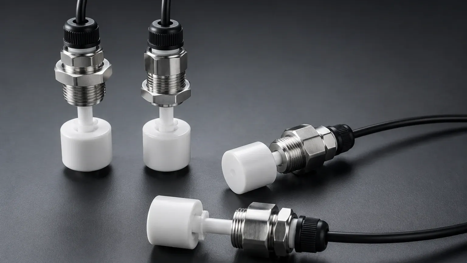
The most traditional form of level detection, the magnetic float switch, utilizes a permanent magnet sealed within a float. As the liquid level rises or falls, the float moves along a stem. Inside the stem, a reed switch is positioned at a predetermined height. When the magnet in the float reaches the reed switch, the magnetic field causes the contacts to close (or open), completing the 12V circuit. This technology is valued for its simplicity and lack of power consumption in the standby state.
2. Vibrating Fork (Tuning Fork) Principle
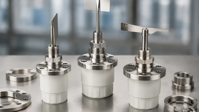
Vibrating level switches use piezoelectric crystals to energize a metal fork at its natural resonant frequency. When the fork is immersed in a liquid or solid, the frequency changes or the vibration is dampened. The internal electronics detect this shift and trigger the switch. For a level switch 12v, the electronics must be designed to operate efficiently within a narrow voltage window, typically providing a PNP or NPN transistor output.
3. Capacitive Principle
Capacitive switches treat the sensor probe and the tank wall (or a reference probe) as two plates of a capacitor. The dielectric constant of the air differs significantly from that of most liquids or solids. As the material covers the probe, the capacitance increases. This change is processed by the internal circuitry to signal a level change. These are particularly useful for non-conductive liquids and bulk solids.
4. Ultrasonic Gap Principle
Ultrasonic point-level switches utilize a pair of crystals (transmitter and receiver) separated by a small gap. When the gap is filled with air, the ultrasonic signal is attenuated and does not reach the receiver. When liquid fills the gap, the signal travels across efficiently. This technology is ideal for clean liquids where mechanical movement must be avoided.
The Role of 12V DC in Industrial Applications
The requirement for a level switch 12v often arises from specific infrastructure constraints. In remote water treatment sites or oil and gas wellheads, power is frequently provided by 12V lead-acid or lithium-ion batteries charged by solar panels. Similarly, in the automotive and maritime industries, 12V is the standard bus voltage.
Using a native 12V device eliminates the need for inefficient voltage converters or step-up transformers, which can introduce heat and electrical noise into the system. However, engineers must account for the fact that a "12V system" often fluctuates between 10.5V (discharged battery) and 14.4V (charging state). A robust industrial level switch must be rated to handle this variance without false triggering or hardware failure.
Technical Selection Criteria
Selecting the correct instrument requires a detailed analysis of both the electrical requirements and the physical properties of the media. Use the following table as a preliminary guide for technology selection.
Technology Comparison Table
| Technology | Media Type | Primary Advantage | Main Limitation |
| :— | :— | :— | :— |
| Magnetic Float | Clean liquids | Low cost, no power required for reed type | Prone to sticking in viscous or scaling fluids |
| Vibrating Fork | Liquids, powders, granules | High reliability, ignores foam and bubbles | Not suitable for very high viscosity (>10,000 cP) |
| Capacitive | Liquids, solids, slurries | No moving parts, can detect through non-metallic walls | Requires calibration for different dielectric constants |
| Optical | Clear, clean liquids | Extremely compact, fast response time | Sensitive to coating and ambient light interference |
| Hydrostatic Switch | Water, oils, chemicals | Simple installation from the top | Density changes affect the switch point accuracy |
Material Compatibility
The wetted parts of the level switch must be compatible with the process media. Common materials include:
* 316L Stainless Steel: The standard for most industrial applications, offering excellent corrosion resistance.
* PP (Polypropylene): Used for acidic or alkaline solutions at lower temperatures (up to 80°C / 176°F).
* PTFE/PVDF: Reserved for highly aggressive chemicals or high-purity applications.
Installation Considerations for 12V Systems
Proper installation is as critical as device selection. For 12V systems, electrical integrity is paramount due to the lower signal-to-noise ratio compared to high-voltage systems.
1. Wiring and Voltage Drop: 12V DC systems are susceptible to voltage drops over long cable runs. For distances exceeding 50 meters (approx. 164 feet), ensure the cable gauge is sufficient (at least 0.75mm² or 18 AWG) to maintain a minimum of 10V at the sensor terminals under load.
2. Orientation: Most float switches can be mounted horizontally or vertically, but vibrating forks must be oriented so that the blades do not trap material. For viscous liquids, the forks should be mounted vertically or at an angle to allow for natural drainage.
3. Turbulence and Sloshing: In tanks with agitators or high inflow rates, mechanical floats may bounce, causing "chatter" in the relay. In these cases, a stilling well (a pipe surrounding the sensor) or a digital delay in the controller should be used.
4. Grounding: Ensure the level switch 12v is properly grounded to the tank or a common ground bus to prevent electrolytic corrosion and to shield the electronics from electromagnetic interference (EMI).
Operational Limitations and Risks
While 12V level switches are versatile, they are not without limitations. Engineers should be aware of the following risks:
* Inductive Loads: If the 12V switch is directly controlling a pump or a solenoid valve, the "back EMF" (voltage spike) generated when the inductive load is turned off can weld reed switch contacts or fry transistor outputs. Always use a flyback diode or an intermediate power relay.
* Temperature Extremes: Standard electronics in 12V switches are often rated for -40°C to +85°C (-40°F to 185°F). If the process temperature exceeds this, remote-mounted electronics or high-temperature extensions are required.
* Coating and Buildup: In applications like wastewater or cement silos, material can build up on the sensor. Vibrating forks and capacitive sensors are generally better at handling buildup than floats, but they still require periodic inspection.
Frequently Asked Questions (FAQ)
Q: Can a 12V level switch be used with a 24V PLC input?
A: Generally, no. Most 24V PLC inputs require a logic high signal of at least 15-18V. Using a 12V switch would require an interposing relay or a signal conditioner to boost the voltage to the level required by the PLC.
Q: Is a level switch 12v safe for explosive atmospheres?
A: Voltage alone does not determine safety. For hazardous areas (Class I, Div 1 or ATEX Zone 0/1), the switch must be certified as Intrinsically Safe (IS) and used in conjunction with a safety barrier, regardless of whether it is 12V or 24V.
Q: How do I test a 12V reed-type float switch?
A: Use a multimeter set to the continuity or resistance (Ohms) setting. Move the float manually; the resistance should toggle between infinity (open) and near-zero (closed). Do not test with a high-voltage insulation tester (Megger), as this will destroy the reed contacts.
Q: What is the difference between NPN and PNP outputs in 12V switches?
A: This refers to the transistor polarity. A PNP switch "sources" power (outputs +12V when triggered), while an NPN switch "sinks" power (connects the output to the negative/ground when triggered). PNP is more common in European and North American industrial systems.
Conclusion
The integration of a level switch 12v into an industrial process requires a balance of electrical engineering and fluid dynamics knowledge. By selecting the appropriate measurement principle—whether it be the mechanical simplicity of a float or the advanced solid-state logic of a vibrating fork—operators can ensure precise point-level control in even the most remote or power-constrained environments. For complex applications involving aggressive chemicals or high-pressure vessels, consulting with a specialist manufacturer like Welk ensures that the selected instrument meets the specific safety and performance standards of the industry.