6 Switches
6 Switches
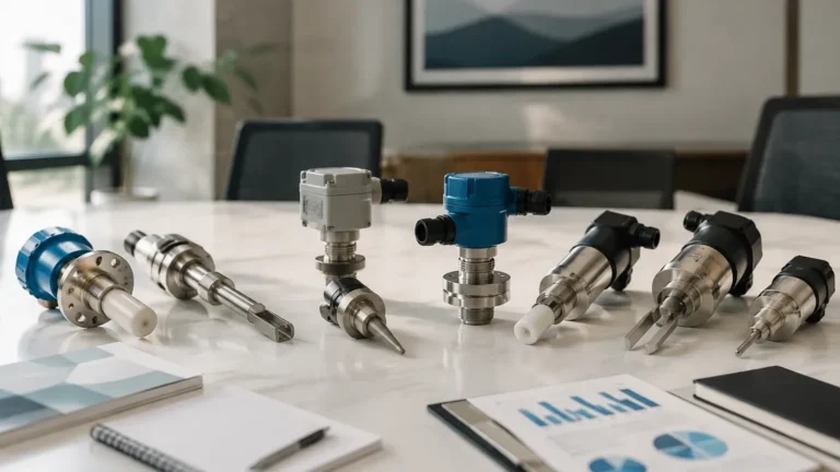
In industrial process control, point level detection serves as the critical safety net for automation systems. While continuous level measurement provides a real-time data stream of vessel contents, level switches provide the discrete signals necessary for pump control, overflow prevention, and dry-run protection. In complex applications—such as multi-stage chemical dosing, sequential filling, or high-redundancy safety systems—the integration of 6 switches or six distinct detection points within a single process environment is a common engineering requirement.
This guide examines the principles of point level measurement, the technical configurations for multi-point setups, and the selection criteria for implementing Level Switches in demanding industrial sectors.
Principles of Point Level Measurement
Before selecting a multi-point configuration, it is essential to understand the physical principles that govern how these instruments detect the presence or absence of a medium. Point level detection relies on the change in a physical property when the sensor comes into contact with a liquid or solid.
Mechanical and Magnetic Principles
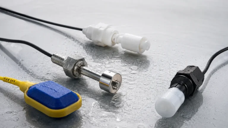
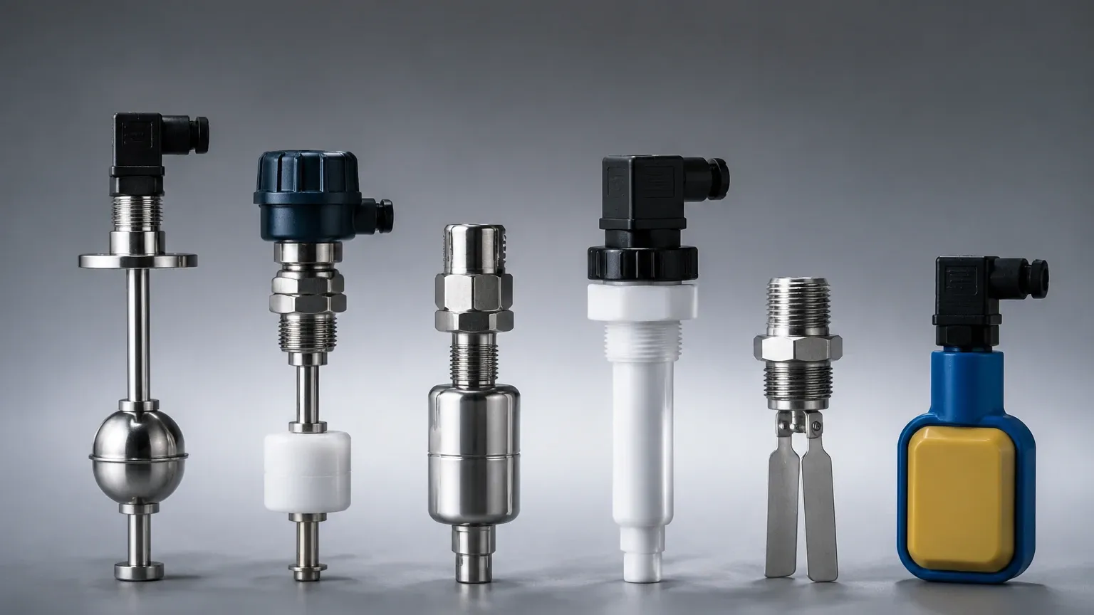
Float level switches are among the most common technologies for multi-point detection. They operate on the principle of buoyancy. A float containing a permanent magnet moves along a stationary stem. Inside the stem are hermetically sealed reed switches. As the float reaches the position of a reed switch, the magnetic field causes the switch to open or close. For systems requiring 6 switches, a single long stem can be engineered with six reed switches positioned at specific intervals, providing a compact solution for multi-level monitoring.
Vibrating (Tuning Fork) Principles
Vibrating level switches use piezoelectric crystals to energize a tuning fork at its natural resonant frequency. When the fork is immersed in a medium, the frequency shifts or the amplitude of vibration is dampened. The internal electronics detect this change and convert it into a switching signal. Unlike float switches, these are typically single-point devices. Implementing a 6-switch logic using this technology usually involves installing six individual sensors at different heights or using a specialized manifold.
Capacitance and Conductivity
Capacitive sensors measure the change in electrical capacitance between the sensor electrode and the tank wall (or a reference electrode). When the medium covers the probe, the dielectric constant changes, triggering the switch. Conductive switches, used only for conductive liquids, rely on the medium completing an electrical circuit between two electrodes. These are often used in multi-rod configurations where up to 6 switches can be represented by six rods of varying lengths.
The Role of 6 Switches in Process Control
Why would a process engineer require a configuration involving 6 switches? The complexity of modern industrial automation often demands more than just a simple "high" and "low" alarm. A six-point logic allows for sophisticated control strategies:
1. Low-Low (LL) Alarm: The absolute minimum level, used to trigger an emergency shutdown of pumps to prevent cavitation and dry-running.
2. Low (L) Level: The setpoint to initiate a tank refill or start a supply pump.
3. Intermediate Level 1: Often used for dosing or mixing transitions where a specific volume must be reached before adding a second reagent.
4. Intermediate Level 2: Used for process pacing or to switch from a high-flow fill to a precision-flow fill.
5. High (H) Level: The setpoint to stop the filling process or close an inlet valve.
6. High-High (HH) Alarm: A redundant safety level that triggers an independent overfill protection system, often linked to a physical siren or a Safety Instrumented System (SIS).
By utilizing 6 switches, plants can achieve a high degree of granularity in their batch processing and ensure that equipment is protected by multiple layers of redundancy.
Technology Selection Matrix
Choosing the right technology for a multi-point application depends on the media properties and the vessel geometry. The following table provides a comparison of common level switch technologies used in multi-point (up to 6 points) configurations.
| Technology | Suitable Media | Max Pressure | Max Temp | Advantages | Limitations |
| :— | :— | :— | :— | :— | :— |
| Multi-Point Float | Clean liquids, oils | Up to 4.0 MPa | 150°C | Cost-effective, up to 6 points on one stem | Prone to scaling/fouling |
| Tuning Fork | Liquids, powders, granules | Up to 6.4 MPa | 250°C | No moving parts, ignores foam | Requires separate units for each point |
| Conductivity Probes | Conductive liquids (water, acids) | Up to 2.0 MPa | 100°C | Simple, no moving parts | Only for conductive media |
| Capacitance | Liquids, solids, slurries | Up to 10.0 MPa | 400°C | High temp/pressure capability | Requires calibration per medium |
| Optical | Clear liquids | Up to 5.0 MPa | 125°C | Very small footprint | Affected by coating or bubbles |
Engineering Considerations for Multi-Point Configurations
When designing a system that incorporates 6 switches, several engineering factors must be addressed to ensure long-term reliability and accuracy.
Wetted Materials and Compatibility
The materials in contact with the process medium (the wetted parts) must be chemically compatible. Common materials include:
* 316L Stainless Steel: Standard for water, oils, and mild chemicals.
* Polypropylene (PP) / PVC: Used for corrosive acids and bases at lower temperatures.
* PTFE/PFA Coating: Essential for highly aggressive chemical environments or where non-stick properties are required to prevent buildup.
Mounting and Orientation
For a system with 6 switches, the mounting method is critical. Top-mounting is the most common for multi-point float or conductivity probes, as it allows a single entry point into the vessel. If using individual tuning forks or capacitive switches, side-mounting at six different elevations is required. Engineers must ensure there is sufficient clearance from agitators, internal baffles, and the tank wall to prevent false triggering or mechanical damage.
Electrical Integration
Managing the signals from 6 switches requires organized wiring. In many B2B industrial settings, these switches are wired back to a PLC (Programmable Logic Controller) or a DCS (Distributed Control System).
* Dry Contacts: Most level switches provide a SPDT or DPDT relay output.
* Two-Wire DC: Often used for intrinsically safe circuits in hazardous areas.
* Bus Systems: Advanced switches may use IO-Link or Modbus to communicate multiple states over a single cable, reducing wiring costs for 6-point setups.
Installation and Maintenance Best Practices
To maintain the integrity of a 6-switch system, follow these practical guidelines:
1. Avoid Turbulence: Do not install level switches directly in the path of the filling stream. If turbulence is unavoidable, use a stilling well (a perforated pipe) to protect the sensor and provide a stable surface for measurement.
2. Minimum Distance: In multi-point float stems, ensure there is a minimum distance (typically 50 mm to 100 mm) between each of the 6 switches to prevent magnetic interference between the floats.
3. Grounding: Ensure the instrument and the tank are properly grounded, especially when using capacitive or conductive switches, to prevent electrical noise from causing false trips.
4. Regular Testing: Safety-critical switches (HH and LL) should be part of a proof-testing schedule. For float switches, this may involve manually lifting the float; for electronic switches, many models include a test button or a magnetic test point to simulate a high-level condition.
Limitations and Risks
While point level switches are reliable, they are not universal solutions. Engineers should be aware of the following risks:
* Build-up: In viscous or sticky media, material can accumulate on the sensor. For float switches, this can cause the float to jam. For tuning forks, excessive build-up can mimic the presence of the medium.
* Density Changes: Float switches are calibrated for a specific specific gravity (SG). If the process fluid changes (e.g., switching from an oil with an SG of 0.8 to a chemical with an SG of 1.2), the float may not sit at the correct level relative to the reed switches.
* Mechanical Wear: Any device with moving parts, such as a float switch, has a finite mechanical life. In high-cycle applications, solid-state alternatives like tuning forks are often preferred despite the higher initial cost.
Frequently Asked Questions (FAQs)
Q: Can I get 6 switches on a single probe?
A: Yes, multi-point magnetic float switches and conductivity probes are specifically designed to provide up to 6 (and sometimes more) switching points on a single vertical stem, requiring only one tank nozzle.
Q: How do I handle 6 switches in a hazardous area?
A: You must use switches that are certified as Intrinsically Safe (Ex i) or Explosion-Proof (Ex d). Intrinsically safe systems require the use of isolation barriers in the control cabinet to limit the energy sent to the switches in the field.
Q: What is the advantage of using 6 switches instead of a continuous level sensor?
A: Reliability and simplicity. A level switch provides a direct, hard-wired response to a level condition that does not rely on complex signal processing. In many safety-critical applications, a level switch is required as a backup to a continuous radar or ultrasonic transmitter.
Q: What units are used for specifying switch points?
A: In international engineering, metric units (mm) are standard for specifying the insertion length and the distance of each switch point from the mounting flange. For example, a 2000 mm probe might have 6 switches located at 300 mm, 600 mm, 900 mm, 1200 mm, 1500 mm, and 1800 mm from the top.
Conclusion
Implementing a system with 6 switches provides the necessary data points for sophisticated tank management and safety. Whether utilizing the simplicity of magnetic floats or the robustness of vibrating forks, selecting the correct technology requires a deep understanding of the process media and the physical constraints of the installation. By adhering to established engineering principles and maintenance protocols, these point level solutions ensure the continued safety and efficiency of industrial operations.