Level Switch Oil Jf 302t Parker
Level Switch Oil Jf 302t Parker
In industrial hydraulic systems and lubrication circuits, maintaining the correct fluid level is not merely a matter of operational efficiency; it is a critical safety requirement. The level switch oil JF 302T Parker (often associated with the Parker Hannifin or UCC product lines) represents a standard in point-level detection for oil-based media. These devices are engineered to provide reliable signals when oil levels reach a predetermined high or low point, preventing pump cavitation, dry running, or reservoir overflow.
Understanding the technical specifications, measurement principles, and application limits of these switches is essential for maintenance engineers and system designers. This guide explores the mechanics of float-type level switches, the specific characteristics of the JF 302T series, and how to select the appropriate Level Switches for diverse industrial environments.
Measurement Principles of Float-Type Level Switches
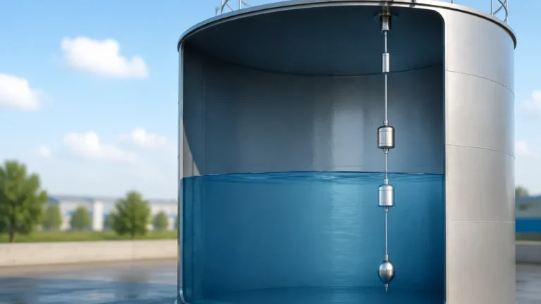
The JF 302T operates on the principle of magnetic buoyancy. This is one of the most established and reliable methods for point-level detection in liquids with stable densities, such as hydraulic oils and lubricants.
The Magnetic Reed Mechanism
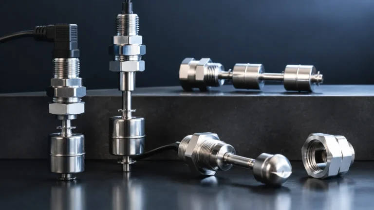
At the core of the device is a hermetically sealed reed switch located within a central stationary stem. A buoyant float, containing a permanent magnet, slides up and down the stem as the liquid level changes. When the float reaches the position of the reed switch, the magnetic field causes the reed contacts to close (or open, depending on the configuration), completing or interrupting an electrical circuit.
Normally Open vs. Normally Closed
Most industrial oil level switches, including the JF 302T series, are designed for versatility. By removing a retaining clip and reversing the orientation of the float on the stem, the switching logic can often be changed from Normally Open (NO) to Normally Closed (NC).
* Normally Open (NO): The circuit is open when the float is at the bottom (low level) and closes as the level rises.
* Normally Closed (NC): The circuit is closed when the float is at the bottom and opens as the level rises (often used for low-level alarms to ensure fail-safe operation).
Technical Specifications and Evaluation Criteria
When evaluating the JF 302T or similar oil level switches, several technical parameters must be verified against the system requirements. These switches are typically designed for low-pressure, tank-top mounting applications.
Material Compatibility
The choice of materials is vital for longevity. For oil applications, the following materials are standard:
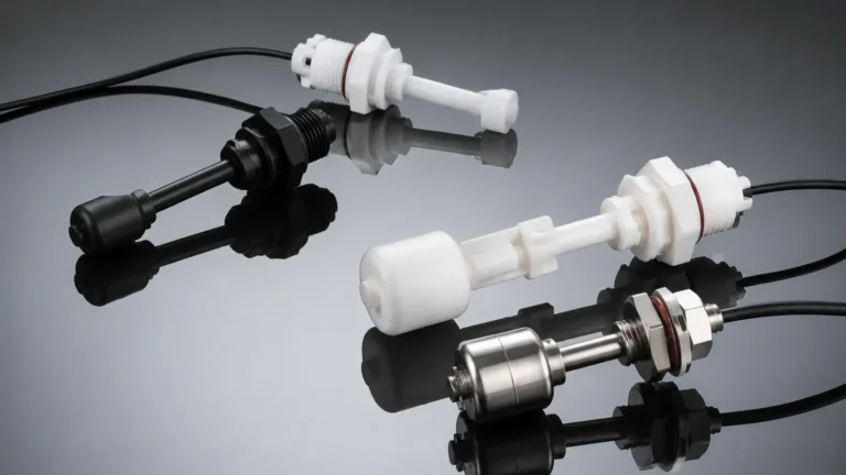
* Float: Often constructed from Nitrile (Buna-N) or cellular NBR, which offers excellent buoyancy and resistance to petroleum-based fluids.
* Stem and Fitting: Typically manufactured from brass or high-grade polymers to prevent corrosion and ensure mechanical stability.
* Gaskets: Usually Nitrile or Viton (FKM) to ensure a leak-proof seal at the mounting point.
Electrical Ratings
Because these switches utilize reed contacts, they are generally intended for signaling rather than direct power switching. Typical ratings include:
* Switching Voltage: Up to 200V DC or 250V AC.
* Switching Current: Generally limited to 0.5A to 1.0A.
* Contact Rating: Often around 10VA to 50VA.
It is a common engineering practice to use these switches in conjunction with a relay to handle higher current loads, such as starting a motor or activating a large solenoid valve.
Practical Selection Table for Oil Level Switches
Choosing the right switch requires balancing environmental factors with the physical properties of the oil. The following table provides a comparison of criteria for standard oil level monitoring.
| Feature | JF 302T / Standard Float | Ultrasonic Level Switch | Optical Level Sensor |
| :— | :— | :— | :— |
| Media Type | Hydraulic/Lubricating Oil | Aqueous & Clean Oils | Clear/Translucent Oils |
| Viscosity Limit | Up to 5,000 cSt | Low to Medium | Low |
| Foam Resistance | Excellent (Float ignores foam) | Poor (Foam scatters signal) | Moderate |
| Max Temperature | 80°C to 100°C (176°F – 212°F) | 70°C (158°F) | 125°C (257°F) |
| Max Pressure | 10 bar (145 psi) | 3 bar (43 psi) | 50 bar (725 psi) |
| Maintenance | Low (Mechanical cleaning) | Very Low (No moving parts) | Moderate (Lens cleaning) |
Installation Considerations for the JF 302T
Proper installation is paramount to prevent false triggering and mechanical failure. For the JF 302T Parker switch, which is typically a vertical mount unit, the following guidelines apply:
1. Vertical Alignment: The switch must be mounted within 30 degrees of vertical. Excessive tilting can cause the float to bind against the stem, leading to a failure to trigger.
2. Turbulence Management: In reservoirs where oil returns at high velocity, the resulting turbulence can cause the float to "chatter." In such cases, the switch should be installed inside a stilling well (a pipe with vent holes) to stabilize the float.
3. Magnetic Interference: Since the switch relies on a magnetic field, it should be kept away from strong electromagnetic sources, such as large motors or transformers, and should not be mounted directly onto ferrous (iron/steel) tank walls without sufficient clearance.
4. Wiring and Protection: Reed switches are sensitive to inductive loads. If the switch is connected to a coil or a long cable run, an RC snubber circuit or a diode (for DC) should be used to prevent contact welding caused by back-EMF.
Limitations and Common Risks
While float switches like the JF 302T are highly reliable, they are not suitable for every environment. Understanding their limitations prevents unexpected downtime.
* Particle Contamination: If the oil contains significant metallic debris (common in some gearbox applications), the magnetic float may attract these particles. Over time, this buildup can weigh down the float or cause it to jam.
* Coating and Buildup: Highly viscous oils or oils that tend to oxidize and form a "varnish" can cause the float to stick to the stem. Regular inspection is required in these applications.
* Physical Shock: Reed switches are made of glass. While protected within the metal or plastic stem, extreme mechanical shock or vibration can cause the reed to break or the contacts to vibrate, causing "signal bounce."
Frequently Asked Questions (FAQ)
Q: Can the JF 302T be used in water?
A: While the materials (Nitrile and Brass) are generally compatible with water, the float is specifically weighted for the specific gravity of oil (typically 0.85 to 0.9). In water (SG 1.0), the float will sit higher, which may slightly shift the switching point, but it will generally function. However, for long-term water use, stainless steel components are preferred to prevent corrosion.
Q: How do I test if the reed switch is functioning?
A: Use a multimeter set to resistance (Ohms) or continuity. Move the float manually along the stem. The resistance should toggle between infinite (Open) and near-zero (Closed). If the resistance remains high when the float is at the trigger point, the reed switch is likely damaged.
Q: What is the standard thread size for these switches?
A: The JF 302T series often utilizes a 1/2" BSP (British Standard Pipe) thread, which is common in European and international hydraulic power units. NPT variants are also available for North American markets.
Advancing Beyond Legacy Switches
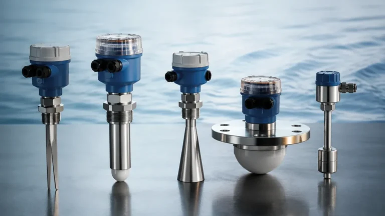
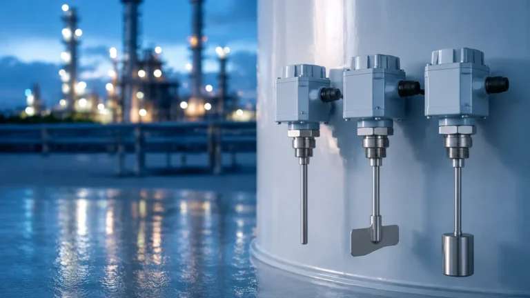
While the JF 302T Parker switch remains a staple for many legacy systems, modern industrial automation often requires more robust data than a simple On/Off signal. Companies like Welk provide a wide range of Level Switches and continuous level transmitters that offer enhanced durability and integration with PLC systems.
For applications involving high-temperature oils (above 100°C) or pressurized vessels, engineers might consider upgrading to stainless steel magnetic level switches or non-contact radar sensors. However, for the vast majority of hydraulic reservoirs and oil tanks, the simplicity and cost-effectiveness of the magnetic float switch remain unmatched.
Summary of Best Practices
To ensure the longest service life for an oil level switch, always verify the chemical compatibility of the float material with the specific additives in your hydraulic fluid. Ensure that the electrical load does not exceed the reed switch's VA rating, and implement a routine maintenance schedule to check for float mobility and sediment buildup. By following these engineering principles, the JF 302T or any equivalent level switch will provide years of reliable service in protecting critical machinery.