6 Level Switch
6 Level Switch
In the landscape of industrial automation and process control, the requirement for granular level monitoring often exceeds the capabilities of a simple high-low alarm system. A 6 level switch configuration—whether achieved through a single multi-point probe or an array of individual sensors—provides six distinct switching points to manage complex fluid dynamics, pump sequencing, and safety redundancies. This level of detail is critical in applications where precise volume management and multi-stage logic are required to prevent dry running, overflows, or process inefficiencies.
Selecting a 6 level switch system requires a deep understanding of the underlying measurement principles, the physical properties of the media being measured, and the mechanical constraints of the vessel. This guide explores the technical frameworks for multi-point level detection and provides engineering benchmarks for selecting the right technology for industrial environments.
Measurement Principles for Multi-Point Detection
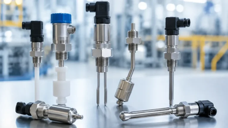
To achieve six distinct switching points, engineers typically rely on one of four primary measurement technologies. Each method has specific strengths depending on the conductivity, viscosity, and chemical aggressiveness of the medium.
1. Magnetic Float Technology
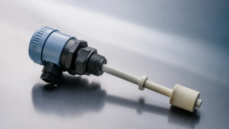
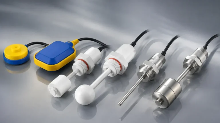
Magnetic float switches are among the most common solutions for multi-point detection. In a 6 level switch probe, a hollow stem contains six hermetically sealed reed switches positioned at specific heights. A float containing a permanent magnet slides along the stem. As the liquid level rises or falls, the float moves, and its magnetic field triggers the reed switches sequentially.
* Advantages: Passive operation (no power required for the switch itself), highly reliable, and relatively low cost.
* Limitations: Susceptible to mechanical jamming if the fluid contains high levels of particulates or becomes highly viscous.
2. Conductivity (Electrode) Principle
For conductive liquids (such as water, acids, or alkalis), a conductivity level switch uses six electrodes of varying lengths, plus a reference electrode. When the liquid touches an electrode, a low-voltage electrical circuit is completed between that electrode and the reference. This signals the controller that a specific level has been reached.
* Advantages: No moving parts, extremely durable in turbulent conditions.
* Limitations: Only works with conductive fluids; electrodes can suffer from scaling or coating in certain chemical environments.
3. Capacitance Level Switching
Capacitance switches measure the change in electrical capacitance between the sensor probe and the tank wall (or a reference probe). While many capacitance switches are single-point, multi-segment probes can be engineered to detect multiple levels. Alternatively, six individual capacitance switches can be installed at different heights.
* Advantages: Can detect non-conductive liquids, oils, and some solids; handles high temperatures and pressures well.
* Limitations: Requires calibration based on the dielectric constant of the media.
4. Ultrasonic and Radar Logic
While technically continuous measurement devices, modern ultrasonic and radar transmitters are frequently used as "virtual" level switches. By programming six distinct setpoints into the transmitter’s software, the device can trigger six different relays or digital outputs. This effectively creates a 6 level switch system without needing six physical sensors.
* Advantages: Non-contact measurement, high precision, no wear and tear.
* Limitations: Higher initial cost; performance can be affected by foam or heavy vapors.
The Logic of 6-Point Level Control
Why use exactly six points? In complex tank management, a 6-level configuration typically follows a standardized logic pattern to ensure both process efficiency and safety. A common setup includes:
1. Level 1 (Low-Low / Dry Run Protection): The absolute minimum level. Triggers an emergency stop for pumps to prevent cavitation or damage.
2. Level 2 (Pump Start/Stop – Low): The lower boundary for normal operation. In a filling application, this triggers the pump to turn on.
3. Level 3 (Mid-Low): Often used for inventory management or to trigger a second "lead" pump in a duplex system.
4. Level 4 (Mid-High): Serves as a warning point or triggers the shutdown of a secondary pump.
5. Level 5 (High / Fill Stop): The upper boundary for normal operation. Triggers the pump to stop or a valve to close.
6. Level 6 (High-High / Overflow Alarm): The emergency safety point. Triggers an audible alarm and physical interlocks to prevent environmental spills.
Selection Criteria for Industrial Applications
When specifying a Level Switches system for a project, several environmental and physical factors must be evaluated to ensure long-term reliability.
Media Characteristics
* Viscosity: High-viscosity fluids (e.g., heavy oils or syrups) may cause floats to stick. In these cases, non-contact ultrasonic or vibrating fork switches are preferred.
* Conductivity: If the fluid is non-conductive (e.g., deionized water or hydrocarbons), conductivity probes will not function.
* Corrosivity: For aggressive chemicals, the wetted parts must be constructed from compatible materials such as 316L stainless steel, PTFE, or PVDF.
Process Conditions
* Temperature: Standard float switches may be rated up to 120°C (248°F), while specialized ceramic-insulated probes can handle much higher ranges.
* Pressure: In pressurized vessels, the buoyancy of a float changes. The float must be designed to withstand the maximum process pressure without collapsing.
Mechanical Constraints
* Tank Height: For deep tanks (over 3 meters / 9.8 ft), a single rigid probe might be difficult to ship and install. Flexible cable-type probes or individual side-mounted switches may be more practical.
* Turbulence: If the tank has an agitator, the sensor must be shielded by a stilling well to prevent false triggering or mechanical fatigue.
Technical Comparison Table
| Technology | Media Type | Max Temperature | Turbulence Resistance | Maintenance Needs |
| :— | :— | :— | :— | :— |
| Magnetic Float | Clean liquids | Up to 150°C (302°F) | Moderate | Low (check for buildup) |
| Conductivity | Conductive liquids | Up to 200°C (392°F) | High | Low (clean electrodes) |
| Capacitive | Liquids/Solids | Up to 250°C (482°F) | High | Medium (calibration) |
| Ultrasonic | Most liquids | Up to 90°C (194°F) | Low (foam sensitive) | Very Low (non-contact) |
| Vibrating Fork| Most liquids | Up to 150°C (302°F) | High | Low (self-cleaning) |

Installation Considerations
Proper installation is paramount for the accuracy of a 6 level switch. Engineers should adhere to the following guidelines:
1. Vertical Alignment: Multi-point float probes must be installed perfectly vertical (within ±5°) to ensure the float moves freely along the stem.
2. Dead Zones: Be aware of the "dead zone" at the top and bottom of the probe. Usually, the first and last switching points cannot be closer than 50 mm (1.97 in) to the process connection or the end of the rod.
3. Wiring and Integration: A 6 level switch generates six sets of dry contacts or a multiplexed signal. Ensure the control panel (PLC/DCS) has sufficient digital inputs. Using a common return wire can simplify cabling, but check local electrical codes for safety requirements.
4. Mounting Location: Avoid installing switches directly under a fill pipe. The force of the incoming liquid can cause false readings or physical damage to the probe.
Limitations and Potential Risks
While a 6 level switch provides excellent data granularity, there are inherent limitations to consider:
* Coating and Buildup: In applications involving wastewater or slurries, material can build up on the probe. For float switches, this leads to sticking; for conductivity probes, it leads to "bridging," where the switch stays active even after the level drops.
* Fixed Setpoints: Most multi-point float and conductivity probes have fixed switching positions determined at the time of manufacture. If the process requirements change, the entire probe may need to be replaced. For applications requiring flexibility, individual switches or a continuous transmitter with programmable outputs are better choices.
* Specific Gravity: Float-based switches are calibrated for a specific fluid density. If the media changes (e.g., switching from water to a light oil), the float may no longer sit at the correct level relative to the reed switches.
Frequently Asked Questions (FAQ)
Q: Can I adjust the switching points on a 6-point float switch after installation?
A: Generally, no. On most industrial multi-point float probes, the reed switches are fixed inside the stem with epoxy. If adjustability is required, you should use individual side-mounted switches or a continuous level sensor with a programmable controller.
Q: What is the maximum length for a 6 level switch probe?
A: Rigid probes are typically available up to 4 meters (13.1 ft). For longer requirements, flexible cable probes are used, though these are more susceptible to movement in turbulent tanks.
Q: How do I test a 6 level switch without filling the tank?
A: For float switches, you can manually slide the float along the stem if the probe is removed from the tank. For conductivity and capacitance switches, a "test" button is often included on the electronics housing to simulate a triggered state.
Q: Is a 6 level switch suitable for hygienic (food/pharma) applications?
A: Yes, provided the materials are FDA-approved and the design features sanitary connections (like Tri-Clamp) and polished surfaces (Ra < 0.8 μm) to prevent bacterial growth.
By carefully evaluating the measurement principle and installation environment, engineers can implement a 6 level switch system that provides the necessary precision for modern industrial processes. Whether managing a simple water reservoir or a complex chemical reactor, these multi-point solutions offer the reliability required for automated level control.