Level Switch Symbols
Level Switch Symbols
In the complex landscape of industrial process control, clarity in documentation is as vital as the precision of the instruments themselves. Level switch symbols serve as the universal language for engineers, technicians, and system integrators, bridging the gap between a conceptual Process and Instrumentation Diagram (P&ID) and the physical installation on a factory floor. Whether designing a water treatment facility or an oil storage terminal, understanding these symbols is essential for ensuring safety, operational efficiency, and regulatory compliance.
At its core, a level switch is a binary device—it detects whether a substance has reached a specific point and triggers an electrical signal. However, the variety of technologies used to achieve this detection means that a single generic icon is rarely sufficient. This guide explores the diverse world of Level Switches, the principles behind their operation, and the standardized symbols used to represent them in technical documentation.
Measurement Principles and Their Symbolic Representation
Before diving into the specific symbols found on blueprints, it is necessary to understand the physical principles that these symbols represent. Different sensing technologies are chosen based on the media (liquid or solid), pressure, temperature, and chemical compatibility.
Float Level Switches
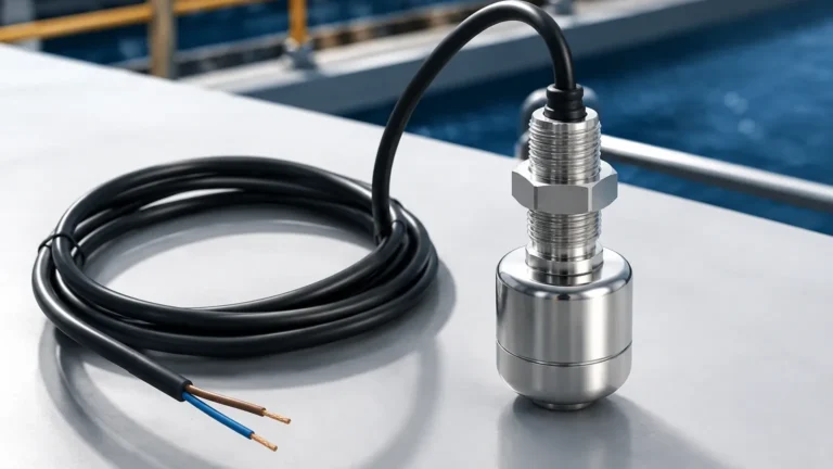
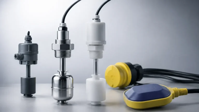
Float switches operate on the principle of buoyancy. A float containing a magnet moves with the liquid level. When it reaches a predetermined point, the magnet actuates a reed switch or a microswitch. In electrical schematics, these are often represented by a symbol featuring a small circle (the float) attached to a switch contact arm.
Vibrating Tuning Fork Switches
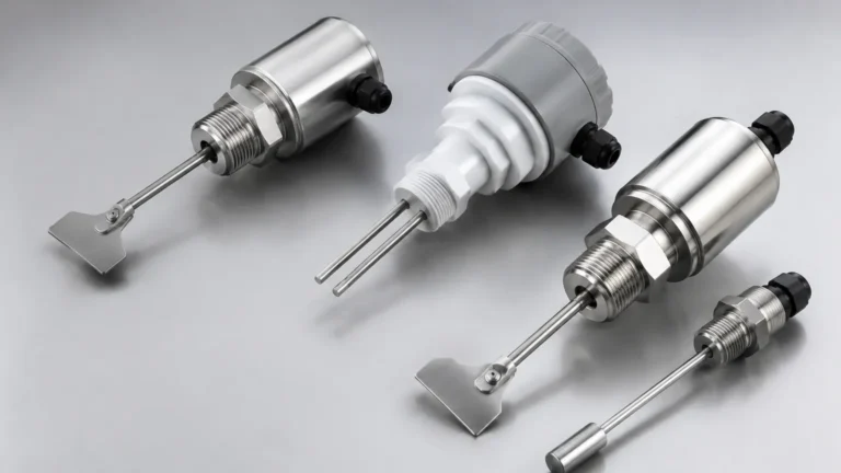
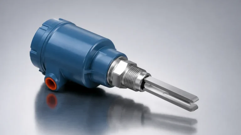
These sensors utilize a fork-shaped element that vibrates at its natural resonant frequency in air. When the fork is submerged in a liquid or covered by a solid, the frequency changes. This change is detected by the internal electronics and converted into a switching signal. Symbols for these often include a "U" or fork-like shape to distinguish them from mechanical floats.
Capacitive Level Switches
Capacitance sensors measure the change in electrical capacitance between the probe and the tank wall (or a reference probe). As the medium rises, the dielectric constant changes, triggering the switch. These are frequently used for both liquids and bulk solids. Their symbols in P&IDs are often categorized by their function (e.g., LSH for Level Switch High) rather than their internal physical mechanism, though electrical diagrams may show a capacitor symbol integrated with the switch.
Conductive Level Switches
Used primarily for conductive liquids like water or acids, these switches rely on the liquid completing an electrical circuit between two electrodes. The symbol typically involves two or more vertical lines representing the probes extending into the process vessel.
Standardized P&ID Symbols for Level Switches
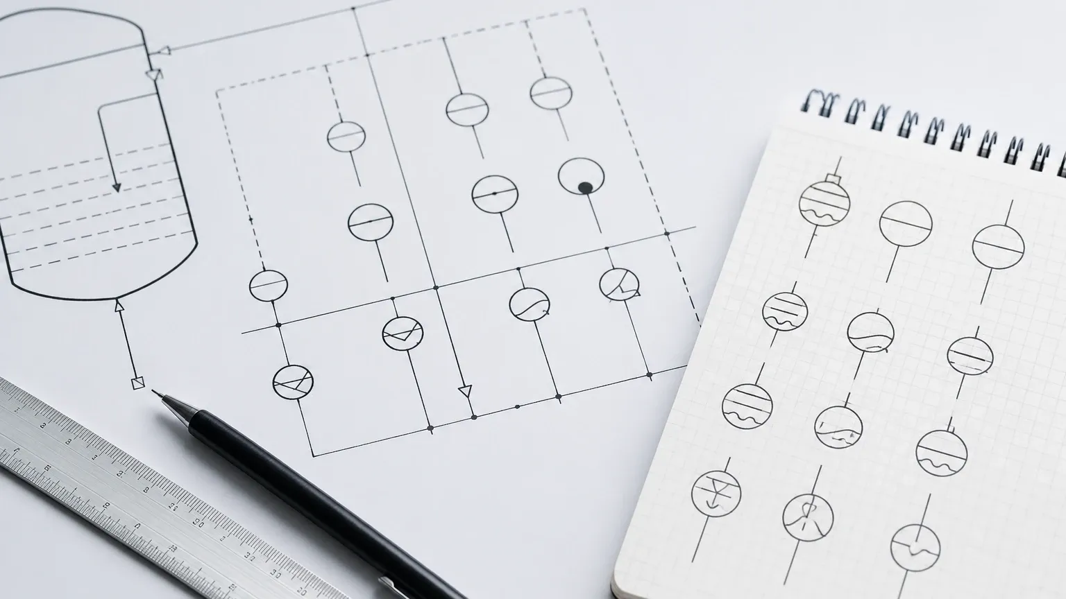
Process and Instrumentation Diagrams (P&IDs) follow standards such as ISA-5.1 to ensure consistency. In these diagrams, a level switch is represented by a circle (a bubble) containing a letter code. The code identifies the function of the instrument.
* LSH (Level Switch High): Triggers when the level rises to a set point, often used for tank overflow prevention.
* LSL (Level Switch Low): Triggers when the level falls below a set point, typically used to prevent pump cavitation or to signal a refill.
* LSHH (Level Switch High-High): An emergency high-level alarm or shutdown switch, usually independent of the primary control loop.
* LSLL (Level Switch Low-Low): An emergency low-level alarm, often used for dry-run protection in heaters or pumps.
In a P&ID, if the circle has no horizontal line, the switch is field-mounted. A single horizontal line indicates it is located in a primary control room, while a double line suggests a secondary or local control panel. A dashed line indicates the instrument is inaccessible or behind a panel.
Electrical Schematic Symbols: IEC vs. ANSI Standards
While P&IDs focus on the process flow, electrical schematics focus on how the device is wired. There are two primary sets of standards: the International Electrotechnical Commission (IEC), common in Europe and Asia, and the American National Standards Institute (ANSI/NEMA), common in North America.
IEC Symbols
IEC symbols tend to be more rectangular and modular. A level switch is often depicted as a contact with a specific mechanical link to a float icon. The contact state is shown in its "de-energized" or "shelf" state (usually the state when the tank is empty or at atmospheric pressure, depending on the specific logic).
ANSI/NEMA Symbols
ANSI symbols use a more representational approach. A high-level switch is often drawn with the "float" icon below the contact, suggesting that as the liquid rises, it pushes the contact closed (Normally Open) or open (Normally Closed). Conversely, a low-level switch icon is drawn above the contact, suggesting it "falls" to actuate.
| Feature | IEC Standard | ANSI/NEMA Standard |
| :— | :— | :— |
| Contact Representation | Rectangular/Linear | Functional/Pictorial |
| Normally Open (NO) | Contact gap horizontal/vertical | "Flag" below or above line |
| Normally Closed (NC) | Line through contact | "Flag" touching the line |
| Common Application | Global/European Projects | North American Projects |
Critical Selection Criteria for Level Switches
Choosing the right level switch involves more than just identifying the correct symbol. Engineers must match the physical properties of the device to the application requirements to ensure the symbol on the drawing performs reliably in the field.
1. Media Properties: Is the liquid viscous, corrosive, or prone to foaming? For example, tuning fork switches are excellent for aerated liquids where floats might fail. For bulk solids, heavy-duty rotary paddle or capacitive switches are preferred.
2. Process Conditions: Standard switches may operate up to 80°C (176°F), but high-temperature variants can handle over 250°C (482°F). Pressure ratings must also be considered, with some industrial switches rated for 40 bar (580 psi) or higher.
3. Output Type: Will the switch drive a PLC input (low current) or a pump motor starter (high current)? Options include Relay (SPDT/DPDT), Transistor (PNP/NPN), or Two-wire electronic switches.
4. Hysteresis: This is the difference between the switch-on point and the switch-off point. It prevents "chattering" where the switch rapidly toggles due to surface turbulence or ripples.
Practical Selection Table
| Technology | Typical Symbol Code | Best For | Limitation |
| :— | :— | :— | :— |
| Float | LSH / LSL | Clean liquids, water tanks | Prone to jamming if solids are present |
| Tuning Fork | LSHH / LSLL | Foaming liquids, powders | Not for very high viscosity media |
| Capacitance | LS | Corrosive chemicals, solids | Requires calibration for different media |
| Conductive | LSH / LSL | Conductive liquids (acids/water) | Cannot be used with oils or distilled water |
| Optical | LS | Small vessels, clear liquids | Sensitive to coating or ambient light |
Installation Guidelines and Best Practices
Correct installation ensures that the physical device matches the logic depicted by the level switch symbols in the engineering drawings.
* Orientation: Some switches, like horizontal floats, must be installed through the side wall of the tank. Others, like tuning forks or vertical floats, can be top-mounted. Ensure the mounting orientation does not create a "dead zone" where the switch cannot detect the level.
* Turbulence and Agitation: If the tank has an agitator or high-velocity inflow, the switch should be installed in a stilling well or protected by a baffle. This prevents mechanical damage and false triggering.
* Wiring and Conduit: Always use the appropriate cable glands to maintain the IP (Ingress Protection) rating of the housing, typically IP65 or IP67 for industrial environments. In hazardous areas, explosion-proof (Ex d) or intrinsically safe (Ex i) wiring methods must be used, and these must be noted near the symbol on the electrical schematic.
* Testing and Calibration: Before commissioning, perform a "dry run" by manually lifting the float or simulating the dielectric change to verify that the signal reaches the control system and that the LSH/LSL logic is correctly configured.
Common Risks and Limitations in Symbol Interpretation
Misinterpreting symbols can lead to significant engineering errors. One common risk is the confusion between Normally Open (NO) and Normally Closed (NC) states. In level measurement, these states are usually defined by the "dry" condition. However, if an engineer assumes a switch is NC when it is actually NO, a safety system designed to stop a pump might fail to actuate, leading to a spill.
Another risk is the failure to distinguish between a control switch and a safety switch. On a P&ID, an LSH might be used for routine pump control, while an LSHH is dedicated to a Safety Instrumented System (SIS). Substituting a standard industrial switch for a SIL-rated (Safety Integrity Level) switch in an LSHH application violates safety protocols, even if the symbols look similar.
Finally, environmental factors like coating (buildup of material on the sensor) can render a switch useless. A symbol on a page does not show that a capacitive probe is covered in dried sludge; regular maintenance and choosing the right technology (like a tuning fork with coating rejection) are the only ways to ensure the symbol remains a truthful representation of the process state.
Frequently Asked Questions (FAQ)
Q: What is the difference between a level switch and a level transmitter in symbols?
A: A level switch (LS) is a discrete device providing an on/off signal. Its symbol is usually a circle with "LS." A level transmitter (LT) provides a continuous signal (e.g., 4-20mA) and is represented by a circle with "LT."
Q: How do I represent a multi-point level switch?
A: For a single probe with multiple switching points (e.g., a float rod with three internal reed switches), the P&ID may show one circle with multiple labels (LSL, LSM, LSH) or multiple circles connected to a single process point.
Q: Are level switch symbols the same globally?
A: No. While ISA-5.1 is widely used, different regions and industries (such as mining vs. pharmaceuticals) may have slight variations. Always check the project's lead symbol sheet or legend.
Q: What does a triangle around a level switch symbol mean?
A: Often, a triangle or a specific border around the instrument bubble indicates that the device is part of a safety-critical loop or a Safety Instrumented Function (SIF).
Q: Can a level switch symbol represent both liquid and solid applications?
A: Yes, the functional symbols (LSH/LSL) are the same. However, the specific technology symbol in the detailed electrical or hook-up drawing will change to reflect whether it is a rotary paddle (solids) or a float (liquids).