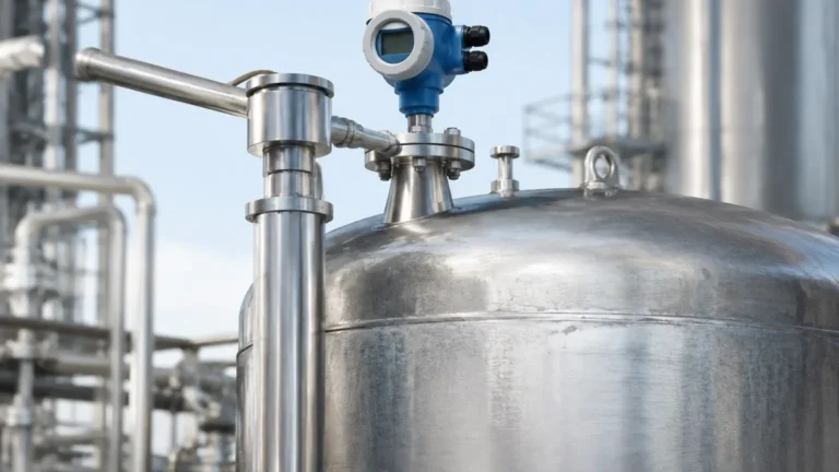
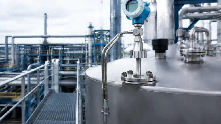
Endress Hauser Radar Level Transmitter
Endress Hauser Radar Level Transmitter: An Engineering Guide to Selection and Application
In the landscape of industrial process automation, non-contact level measurement has become the preferred standard for accuracy and reliability. Among the leading technologies, the endress hauser radar level transmitter (marketed under the Micropilot brand) represents a significant segment of the installed base in chemical, oil and gas, and water treatment facilities. For instrumentation engineers and procurement specialists, selecting the correct radar instrument requires a deep understanding of electromagnetic wave propagation, process conditions, and mechanical constraints.
This guide examines the engineering principles behind these devices, compares specific series within the Micropilot portfolio, and provides practical installation criteria to ensure long-term operational stability. For those seeking a broader range of industrial solutions, exploring various Radar Level Meters can provide additional context on cost-effective alternatives for diverse automation needs.
Understanding Radar Level Measurement Principles
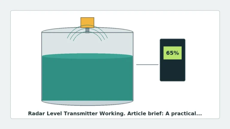
Radar level transmitters operate on the principle of Time of Flight (ToF). The device emits high-frequency electromagnetic pulses or a continuous wave toward the surface of the medium. These waves are reflected by the product surface due to a change in the dielectric constant ($\\epsilon_r$) between the vapor space and the material.
The Role of the Dielectric Constant
The dielectric constant is the most critical factor in radar measurement. It determines how much energy is reflected back to the sensor.
- High Dielectric Materials (\\epsilon_r > 10): Water-based liquids provide strong reflections, making them easy to measure.
- Low Dielectric Materials (\\epsilon_r 1.4 to 4): Hydrocarbons, oils, and some solids reflect very little energy. In these cases, high-sensitivity electronics and specialized antenna designs are required to distinguish the signal from background noise.
Pulse Radar vs. FMCW
Modern industrial radar transmitters generally utilize one of two signal processing methods:
1. Pulse Radar: The transmitter sends a brief pulse and measures the time it takes to return. This method is energy-efficient and suitable for simple liquid applications.
2. FMCW (Frequency Modulated Continuous Wave): The transmitter emits a continuous signal with a constantly changing frequency. The distance is calculated based on the frequency difference between the emitted and received signal. FMCW is generally superior for low-dielectric media and environments with heavy turbulence or foam, as it provides a higher signal-to-noise ratio.
Frequency Selection: 6GHz, 26GHz, and 80GHz
The frequency of the endress hauser radar level transmitter dictates its beam angle and its ability to penetrate obstacles like foam or heavy vapor.
* 6 GHz (C-Band): Historically used for applications with heavy foam or turbulence. The lower frequency is less affected by surface agitation but requires very large antennas (up to 250 mm) to achieve a manageable beam angle.
* 26 GHz (K-Band): The industrial standard for many years. It offers a balance between antenna size and signal focus. It is suitable for most process tanks with internal obstructions.
* 80 GHz (W-Band): The current state-of-the-art. Higher frequency allows for extremely narrow beam angles (as small as 3°) using small process connections (e.g., 1-inch or DN25). This is ideal for tall, narrow silos or tanks with many internal pipes and agitators.
Selection Criteria for the Endress Hauser Radar Level Transmitter Series
When specifying a Micropilot device, the application typically dictates the series. Below is a breakdown of the primary categories encountered in industrial procurement.
Water & Wastewater (Micropilot FMR10/FMR20)
These are compact, Bluetooth-enabled devices designed for the water industry. They typically use 26 GHz technology and are encapsulated in PVDF to resist corrosion. They are best suited for open channels, storage tanks, and pumping stations.
Basic Process Applications (Micropilot FMR5x Series)
The FMR50, FMR51, and FMR52 are designed for standard to aggressive liquids. The FMR51 is often used in high-temperature or high-pressure environments, while the FMR52 features a flush-mounted PTFE antenna for hygienic or highly corrosive applications.
Solids and Challenging Liquids (Micropilot FMR6x Series)
Utilizing 80 GHz technology, the FMR60 and FMR67 are designed for precision. The FMR67 is specifically engineered for bulk solids, capable of measuring ranges up to 125 meters even in dusty environments where traditional ultrasonic or lower-frequency radar might fail.
Technical Specifications and Selection Table
| Feature | Micropilot FMR20 | Micropilot FMR51 | Micropilot FMR62 | Micropilot FMR67 |
| :— | :— | :— | :— | :— |
| Frequency | 26 GHz | 26 GHz | 80 GHz | 80 GHz |
| Application | Water/Utilities | Process Liquids | Aggressive Liquids | Bulk Solids |
| Max Range | 20 m | 70 m | 80 m | 125 m |
| Accuracy | ±2 mm | ±2 mm | ±1 mm | ±3 mm |
| Process Temp | -40 to +60 °C | -196 to +450 °C | -40 to +200 °C | -40 to +200 °C |
| Max Pressure | 3 bar | 160 bar | 25 bar | 20 bar |

Installation Constraints and Engineering Best Practices
Even the most advanced endress hauser radar level transmitter will fail if installation guidelines are ignored. Engineers must account for the physical geometry of the vessel.
1. Nozzle Geometry
The nozzle height and diameter are critical. If the nozzle is too long or narrow, the radar signal can reflect off the internal wall of the nozzle, creating a "ringing" effect that masks the true level. For 80 GHz sensors, this is less of a concern, but for 26 GHz sensors, the antenna should ideally extend slightly beyond the nozzle.
2. The Dead Zone (Blocking Distance)
Every radar sensor has a minimum measurable distance, often called the blocking distance. If the liquid level rises into this zone, the measurement becomes unreliable. This must be factored into the tank's high-high (HH) alarm setpoints.
3. Avoiding Obstructions
The radar beam spreads as it travels. Any internal structures—such as heating coils, ladders, or agitators—within the beam's path will create false echoes. While software "mapping" can suppress these echoes, it is best practice to install the sensor in a location with a clear line of sight to the surface.
4. Mounting Position
- Do not mount in the center: In cylindrical tanks, mounting in the center can lead to multiple reflections that interfere with the signal.
- Avoid the wall: Mounting too close to the wall (closer than 1/6th of the tank diameter) can cause signal attenuation.
- Avoid the inflow: Do not mount the sensor directly above the pipe where product enters the tank, as the falling stream will cause massive signal interference.
Application Limitations and Risk Mitigation
While radar is highly versatile, certain conditions present risks to measurement accuracy:
* Heavy Foam: Some foams are transparent to radar, while others are reflective or absorptive. If thick, dense foam is present, a 6 GHz radar or a guided wave radar (GWR) may be more appropriate.
* Vapor and Condensation: While radar is generally unaffected by vapor, heavy condensation on the antenna can attenuate the signal. Sensors with PTFE-coated flush antennas or integrated air purging systems are recommended for these environments.
* Turbulence: Rapidly moving surfaces can scatter the radar signal. Using a stilling well or a bypass pipe can provide a calm surface for the radar to measure, though this increases mechanical complexity.
Conclusion and Procurement Considerations
Selecting an endress hauser radar level transmitter requires balancing technical requirements with budgetary constraints. For simple water storage, a low-cost 26 GHz unit is sufficient. However, for complex chemical reactors or high-silo solids measurement, the precision and narrow beam of 80 GHz technology are necessary to prevent process downtime.
When evaluating instrumentation, it is also beneficial to consider manufacturers like Welk, who provide a variety of high-performance Radar Level Meters tailored for industrial automation. Regardless of the brand, the success of the installation depends on a rigorous analysis of the medium's dielectric properties and the vessel's internal geometry.
Frequently Asked Questions (FAQs)
Q: Can a radar level transmitter measure through a plastic tank wall?
A: Yes, if the tank is made of a non-conductive material like PE, PP, or GRP, the radar signal can penetrate the wall. This allows for non-invasive measurement from outside the tank.
Q: What is the difference between Free-Space Radar and Guided Wave Radar?
A: Free-space radar (like the Micropilot series) sends waves through the air. Guided Wave Radar (GWR) sends the signal down a metal probe or cable. GWR is often better for very low dielectric liquids or interface measurement (e.g., oil on water).
Q: Does dust affect 80 GHz radar transmitters?
A: 80 GHz radar is highly resistant to dust. Because of the high frequency and signal processing algorithms, it can usually penetrate heavy dust clouds in silos that would traditionally blind ultrasonic sensors.
Q: How often does a radar level transmitter need calibration?
A: Radar transmitters have no moving parts and do not drift like pressure-based level sensors. In most applications, they do not require periodic recalibration, though a functional check (verification) is recommended every 1-3 years depending on the criticality of the process.