Radar Level Transmitter Full Form
Radar Level Transmitter Full Form: A Technical Engineering Guide
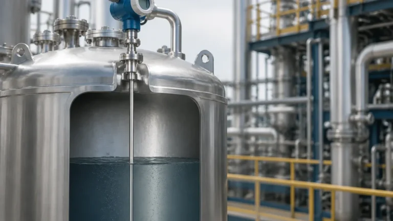
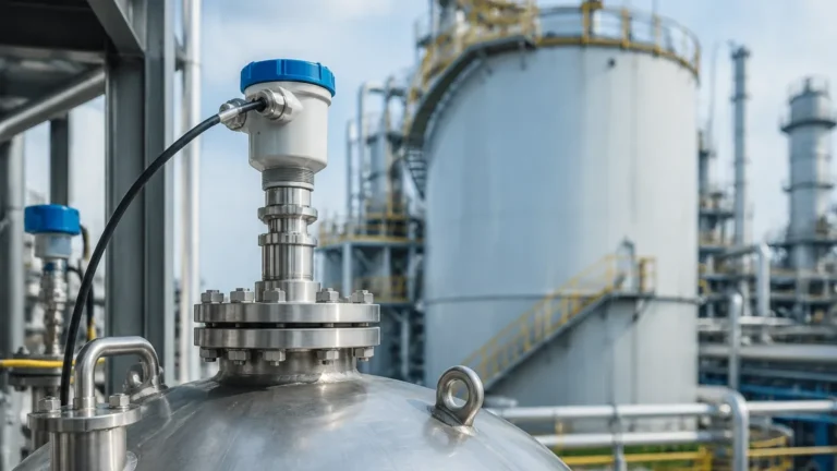
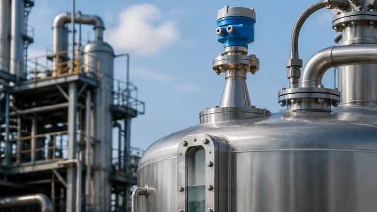
In the field of industrial process control, understanding the radar level transmitter full form and its operational mechanics is essential for engineers and procurement professionals. While "full form" often refers to the literal expansion of the acronym, in a technical context, it encompasses the complete functional definition: a device that utilizes electromagnetic waves to measure the distance to a material surface, converting that distance into a standardized electronic signal (typically 4-20mA or digital protocols like HART/RS485) for level monitoring and control.
Radar Level Meters represent the pinnacle of non-contact level measurement technology. They are engineered to operate in environments where traditional sensors—such as ultrasonic or hydrostatic transmitters—might fail due to temperature extremes, vacuum conditions, or heavy dust. This guide explores the principles, selection criteria, and installation requirements for these critical industrial instruments.
Measurement Principles of Radar Level Technology
Before selecting a device, it is vital to understand how radar energy interacts with the process medium. Radar level transmitters operate on the principle of Time of Flight (ToF). The device emits high-frequency electromagnetic pulses or continuous waves that travel at the speed of light. When these waves encounter a change in the dielectric constant ($ε_r$)—typically the transition from air to the surface of a liquid or solid—a portion of the energy is reflected back to the sensor.
There are two primary methods used in modern industrial radar systems:
1. Pulse Radar (Non-Contact)
Pulse radar transmitters emit short bursts of microwave energy. The electronic circuit measures the time interval between the emission of the pulse and the reception of the echo. Because the speed of light is constant, the distance is calculated using the formula:
Distance = (Speed of Light × Time of Flight) / 2
Pulse radar is often used in simple liquid applications and is known for its energy efficiency, making it suitable for battery-powered or loop-powered installations.
2. Frequency Modulated Continuous Wave (FMCW)
FMCW radar does not send pulses. Instead, it emits a continuous signal where the frequency changes linearly over time (a frequency sweep). The reflected signal is compared to the emitted signal at that exact moment. The difference in frequency (Δf) is directly proportional to the time delay, and thus the distance. FMCW is generally more accurate than pulse radar and is the preferred technology for high-precision applications, such as custody transfer or measuring materials with low reflectivity.
3. Guided Wave Radar (GWR)
Unlike non-contact radar, GWR uses a physical probe (rod or cable) to guide the microwave signal to the surface. This concentrated energy path allows GWR to measure materials with very low dielectric constants ($ε_r$ as low as 1.4) and is unaffected by surface turbulence, foam, or tank internal obstructions.
Technical Selection Criteria
Choosing the correct radar level transmitter requires a detailed analysis of the process environment. The following factors are decisive for performance:
Frequency Bands
The frequency of the radar signal determines the beam angle and the ability to penetrate dust or steam.
* 6 GHz (C-Band): Features a wide beam angle. It is highly resistant to foam and heavy vapors but requires larger antennas (up to 250mm) to maintain focus.
* 26 GHz (K-Band): The industrial standard for most liquid and solid applications. It offers a balance between antenna size and signal focus.
* 80 GHz (W-Band): The latest advancement in radar technology. It provides a very narrow beam angle (as small as 3°), allowing for installation in narrow tanks with internal obstructions or through small nozzles. It also offers superior accuracy in measuring solids with steep angles of repose.
Dielectric Constant (ε_r)
The dielectric constant of the medium determines how much energy is reflected. Water has a high dielectric constant (~80), making it very easy to measure. In contrast, hydrocarbons and oils have low dielectric constants (2.0 to 4.0), which may require high-sensitivity FMCW transmitters or Guided Wave Radar.
Process Conditions
* Temperature: Industrial radars can handle temperatures ranging from -40°C to +450°C, depending on the flange and seal materials.
* Pressure: Standard units handle atmospheric pressure, while specialized high-pressure versions can operate up to 400 bar (40 MPa).
* Corrosion: For aggressive chemicals like hydrochloric acid, PTFE-lined antennas or flange-drop antennas are required to prevent sensor degradation.
Selection Table: Radar Technology Comparison
| Feature | Pulse Radar (26GHz) | FMCW Radar (80GHz) | Guided Wave Radar (GWR) |
| :— | :— | :— | :— |
| Accuracy | ±3 mm to ±5 mm | ±1 mm to ±2 mm | ±2 mm |
| Measuring Range | Up to 30 meters | Up to 120 meters | Up to 75 meters (cable) |
| Beam Angle | 8° to 20° | 3° to 6° | N/A (signal follows probe) |
| Foam Resistance | Moderate | Low | High |
| Internal Obstructions | Sensitive | Minimal interference | Unaffected |
| Best Use Case | General liquid storage | Tall silos, narrow tanks | Low dielectric oils, bypass pipes |
Installation Considerations
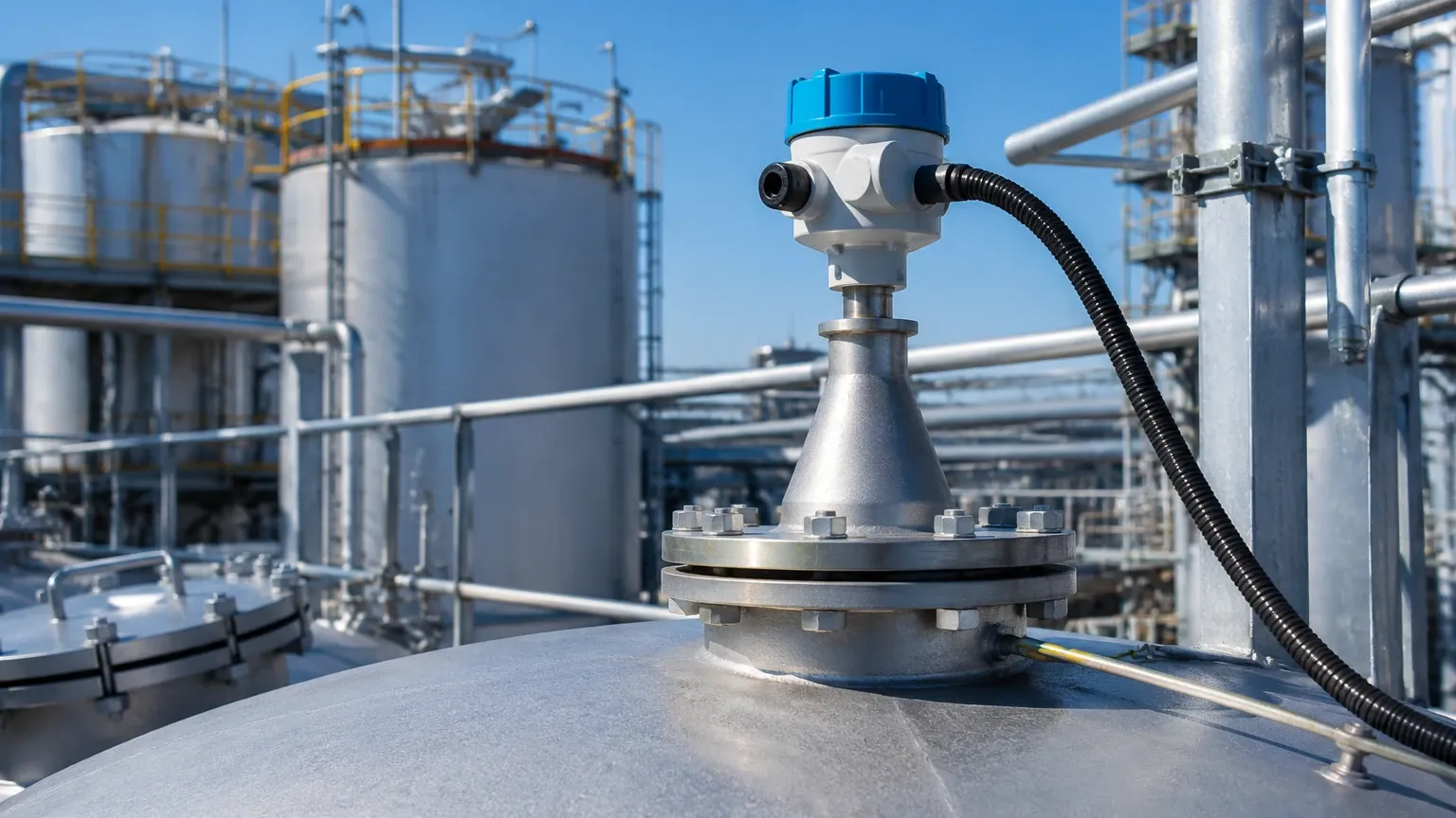
Correct installation is the most critical factor in ensuring the reliability of a radar level transmitter. Engineers must adhere to the following guidelines:
1. Nozzle Positioning: The transmitter should not be installed in the center of a tank (to avoid multiple reflections from the tank walls) nor too close to the wall (to avoid signal attenuation). A common rule is to install the device at 1/4 to 1/6 of the tank diameter from the wall.
2. Obstruction Avoidance: The radar beam must have a clear path to the surface. Avoid installing the sensor directly above agitators, heating coils, or ladders. If obstructions are unavoidable, many modern transmitters offer "false echo suppression" software to map out and ignore these static reflections.
3. Nozzle Height and Diameter: The antenna should ideally extend slightly below the mounting nozzle. If the nozzle is very long, it can cause "ringing" or internal reflections that interfere with the near-range measurement (the "Dead Zone").
4. Solid Materials: When measuring solids (like grain or cement), the sensor should be mounted with an adjustable flange to aim the beam at the material's angle of repose, ensuring the maximum signal return.
Limitations and Application Risks
While radar is highly versatile, it is not a "one-size-fits-all" solution. Technical limitations include:
* Heavy Foam: Extremely thick, dense foam (like that found in some wastewater treatment or fermentation processes) can absorb the radar signal entirely, leading to a "loss of echo" error.
* Vacuum Effects: While the vacuum itself does not affect the speed of the microwave, the transition through a glass or plastic window (if using a non-invasive setup) can cause signal refraction.
* Condensation: Heavy moisture buildup on the antenna lens can attenuate the signal. In these cases, air purging systems or PTFE-coated "drop" antennas are recommended to shed droplets.
Frequently Asked Questions (FAQ)
Q: What is the "Dead Zone" in a radar level transmitter?
A: The Dead Zone, or Blocking Distance, is the area immediately below the sensor where accurate measurement is impossible. This is typically between 50mm and 300mm depending on the frequency and antenna type. Process levels should be managed to stay below this zone.
Q: Can radar measure interface levels?
A: Yes, specifically Guided Wave Radar. If the upper liquid has a lower dielectric constant than the lower liquid (e.g., oil over water), the radar signal will reflect off both the top surface and the interface between the two liquids.
Q: Is 80GHz always better than 26GHz?
A: Not necessarily. While 80GHz offers better precision and smaller antennas, 26GHz or even 6GHz may be better for applications with heavy foam or steam, as the longer wavelengths can penetrate these obstacles more effectively.
Q: Does the color or transparency of the liquid affect the measurement?
A: No. Unlike laser or optical sensors, radar depends entirely on the dielectric constant and is unaffected by the color, transparency, or optical clarity of the medium.
Conclusion for International Buyers
When sourcing equipment, the radar level transmitter full form represents a commitment to precision and safety in industrial automation. For global procurement, it is essential to verify that the manufacturer provides comprehensive calibration certificates and complies with international standards such as ATEX/IECEx for explosive atmospheres or SIL2 for functional safety.
By understanding the nuances between frequency bands and the physical constraints of the installation site, engineers can select a solution that minimizes maintenance and maximizes uptime. For detailed technical specifications and customized configurations, professionals should Review product options and application support to ensure the selected instrumentation aligns with their specific process requirements.