Guided Wave Radar Level Transmitter Working Principle
Guided Wave Radar Level Transmitter Working Principle: A Comprehensive Engineering Guide
In the field of industrial process control, accurate level measurement is fundamental to operational safety, inventory management, and process efficiency. Among the various technologies available, the guided wave radar (GWR) transmitter has emerged as a preferred solution for challenging environments. This article provides a technical deep dive into the guided wave radar level transmitter working principle, its mechanical configurations, and practical selection criteria for industrial applications.
Understanding the Guided Wave Radar Level Transmitter Working Principle
Guided Wave Radar technology is based on the principle of Time Domain Reflectometry (TDR). While traditional Radar Level Meters emit electromagnetic pulses through the air (non-contact), GWR systems utilize a physical probe to guide the signal directly to the process medium.
The Physics of Time Domain Reflectometry (TDR)
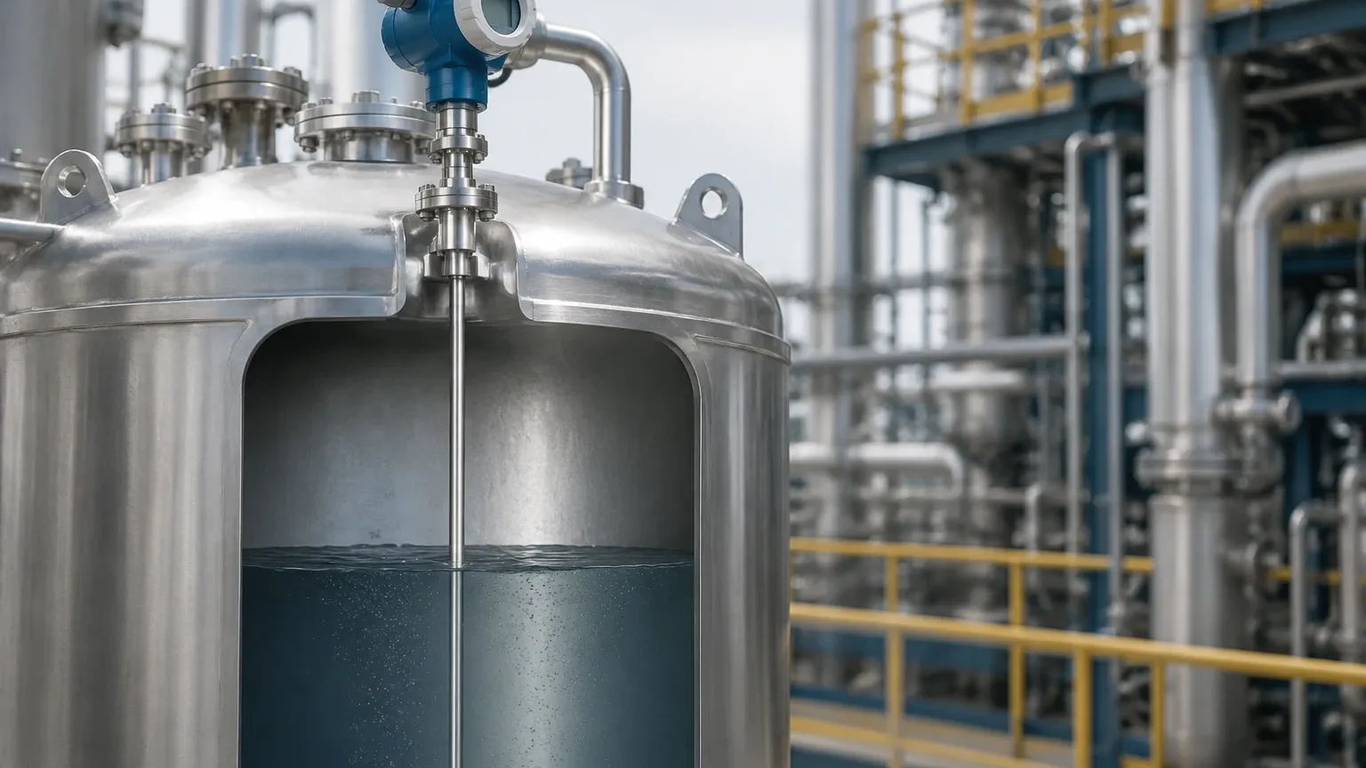
The guided wave radar level transmitter working principle begins with the electronics head generating low-energy, high-frequency electromagnetic pulses. These pulses are transmitted along a probe—a metal rod, cable, or coaxial tube—that acts as a waveguide.
When these pulses travel down the probe and encounter a change in the dielectric constant ($\\varepsilon_r$) of the surrounding environment (typically the transition from air to the liquid or solid medium), a portion of the pulse energy is reflected back to the transmitter.
1. Pulse Emission: The transmitter sends a pulse at the speed of light.
2. Impedance Change: The boundary between the gas phase (dielectric $\\approx$ 1) and the process medium (dielectric > 1.4) causes an impedance mismatch.
3. Reflection: The reflected signal (echo) travels back up the probe.
4. Time-of-Flight Calculation: The transmitter’s microprocessor measures the time interval between the emission of the pulse and the receipt of the echo.
Since the speed of electromagnetic waves is constant, the distance ($D$) to the surface is calculated using the formula:
$$D = \\frac{c \\times t}{2}$$
Where:
* $c$ is the speed of light in the medium (adjusted for the waveguide).
* $t$ is the measured transit time.
By knowing the total tank height (reference point to bottom), the device subtracts the measured distance to determine the level of the product.
The Role of the Dielectric Constant (\\varepsilon_r)
The strength of the reflection is directly proportional to the dielectric constant of the medium. Materials with high dielectric constants, such as water ($\\varepsilon_r \\approx$ 80), reflect a significant portion of the signal, resulting in a very clear echo. Conversely, hydrocarbons and oils often have low dielectric constants ($\\varepsilon_r$ 1.8 to 2.5), which return weaker signals. Modern GWR transmitters are designed with high sensitivity to detect these faint reflections, often capable of measuring media with $\\varepsilon_r$ as low as 1.4.
Interface Measurement Capabilities
One of the most significant advantages of the guided wave radar level transmitter working principle is its ability to measure liquid-liquid interfaces. This is particularly useful in the oil and gas industry, such as in oil-water separators.
If the upper liquid layer has a low dielectric constant (e.g., oil) and the lower layer has a high dielectric constant (e.g., water), the radar pulse will partially reflect off the top surface of the oil. The remaining energy continues through the oil (at a slightly reduced speed due to the oil's dielectric) and reflects off the water interface. By analyzing both echoes, the transmitter can provide the total level and the interface level simultaneously.
Probe Types and Their Applications
The choice of probe is critical to the performance of GWR Radar Level Meters. The probe geometry dictates how the electromagnetic field is distributed around the waveguide.
| Probe Type | Characteristics | Best Use Case |
| :— | :— | :— |
| Coaxial Probe | The signal is entirely contained within the outer tube. Offers the highest Signal-to-Noise Ratio (SNR). | Low dielectric liquids, clean fluids, tanks with internal obstructions. |
| Single Rod/Cable | Simple design, easy to clean, and resistant to build-up. Requires more clearance from tank walls. | Viscous liquids, slurries, and applications prone to coating. |
| Twin Rod/Cable | Two parallel conductors. Better signal focus than single rods but prone to bridging by solids. | Long-range measurements in liquids where coaxial probes are too heavy or expensive. |
Metric Specifications and Limits
* Measuring Range: Typically up to 30 meters (cable probes) or 6 meters (rod probes).
* Temperature Range: Standard models handle -40°C to +200°C; specialized high-temperature versions can reach +450°C.
* Pressure Range: From full vacuum up to 400 bar (40 MPa).
Installation Considerations and Best Practices
To ensure the accuracy of the guided wave radar level transmitter working principle, engineers must adhere to specific installation guidelines. Unlike non-contact radar, GWR is less affected by foam or dust, but physical contact introduces other constraints.
1. Nozzle Dimensions: The nozzle height and diameter should be kept to a minimum to prevent "ringing" or signal interference at the top of the probe. For single rod probes, the nozzle diameter should ideally be at least 50 mm.
2. Obstructions: While the signal follows the probe, the electromagnetic field extends outward. For single rod probes, a clearance of at least 300 mm should be maintained from agitators, ladders, or tank walls to avoid parasitic reflections.
3. Probe Anchoring: In tall tanks with high turbulence, cable probes should be anchored to the bottom to prevent the probe from swinging and hitting the tank wall or internal structures.
4. Bypass Chambers: For extremely turbulent surfaces or boiling liquids, installing the GWR probe inside a bypass chamber or stilling well provides a calm surface for measurement and simplifies maintenance.
Advantages and Limitations
Advantages
* Independence from Vapor and Density: Unlike hydrostatic or ultrasonic sensors, GWR is unaffected by changes in pressure, temperature, or gas phase composition.
* No Moving Parts: Reduces maintenance requirements compared to float-based systems.
* Foam Tolerance: GWR can often see through light foam to measure the true liquid level, or detect the top of dense foam depending on the configuration.
Limitations
* Contact Technology: The probe must be compatible with the process fluid. Corrosive media require specialized coatings like PTFE or PFA.
* Build-up and Bridging: While single rods handle coating well, significant build-up or "bridging" between twin rods or within coaxial tubes can cause false high-level readings.
* Minimum Dielectric: Materials with $\\varepsilon_r < 1.4$ may require a coaxial probe or a stilling well to concentrate the signal sufficiently.
Selection Table for Industrial Media
| Medium Type | Recommended Probe | Considerations |
| :— | :— | :— |
| Deionized Water | Coaxial or Rod | High dielectric makes measurement easy. |
| Crude Oil | Coaxial or Single Cable | Low dielectric; coaxial preferred for accuracy. |
| Chemical Slurries | Single Rod (PTFE coated) | Minimize build-up and corrosion. |
| Plastic Pellets | Single Cable | High tensile strength needed for pull-down forces. |
| Liquefied Gas (LPG) | Coaxial | High pressure and low dielectric require maximum signal focus. |
Frequently Asked Questions (FAQ)
Q: Can a GWR transmitter be used in a plastic tank?
A: Yes, but since plastic tanks do not provide a ground plane, a coaxial probe is recommended, or a dual-rod probe can be used. If using a single rod, a metal flange or mounting plate is necessary to act as a reference.
Q: How does the transmitter handle "dead zones"?
A: Every GWR has an upper and lower dead zone (blocking distance) where measurement is not possible or less accurate. This is usually 100 mm to 300 mm at the top, depending on the probe and nozzle. These should be accounted for during the vessel design phase.
Q: Is it possible to cut the probe to length in the field?
A: Most cable and rod probes can be shortened in the field. However, the transmitter electronics must be reconfigured with the new probe length to maintain accuracy.
Q: Does the probe need to be grounded?
A: The transmitter housing must be grounded to the tank (if metal) to ensure the TDR circuit functions correctly. This is typically achieved through the process connection (flange or thread).
Conclusion
Understanding the guided wave radar level transmitter working principle is essential for selecting the right instrumentation for complex industrial environments. By leveraging Time Domain Reflectometry and physical waveguides, GWR offers a robust, high-precision solution that excels where other technologies fail—particularly in low-dielectric, high-pressure, or interface applications. When specifying Radar Level Meters, engineers should prioritize probe geometry and material compatibility to ensure long-term reliability in the field.
Download Guided Wave Radar Level Transmitter Working Principle as a PDF