Dp vs Radar Level Transmitter
Dp vs Radar Level Transmitter: A Technical Engineering Guide to Industrial Selection
In the field of industrial level measurement, selecting the appropriate technology is critical for process safety, efficiency, and inventory accuracy. Two of the most prevalent technologies used in modern process plants are Differential Pressure (DP) transmitters and Radar Level Meters. While both are capable of providing continuous level data, they operate on fundamentally different physical principles.
Choosing between a dp vs radar level transmitter requires a deep understanding of the process media, vessel geometry, and environmental conditions. This guide provides a technical analysis of both technologies, their measurement principles, and the criteria engineers must evaluate to ensure reliable performance.
1. Measurement Principles
Before comparing the two technologies, it is essential to understand how each derives a level reading.
Differential Pressure (DP) Measurement
DP level transmitters operate on the principle of hydrostatic pressure. According to the laws of physics, the pressure exerted by a liquid column is proportional to its height and its density. The formula used is:
P = ρ × g × h
Where:
* P is the hydrostatic pressure.
* ρ (rho) is the density of the liquid.
* g is the gravitational constant (9.81 m/s²).
* h is the height of the liquid.
In an open tank, the transmitter measures the pressure at the bottom relative to atmospheric pressure. In a pressurized vessel, the transmitter measures the difference between the high-pressure side (bottom of the tank) and the low-pressure side (top of the tank/vapor space) to cancel out the head pressure.
Radar Level Measurement
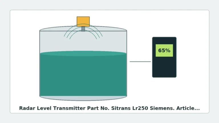
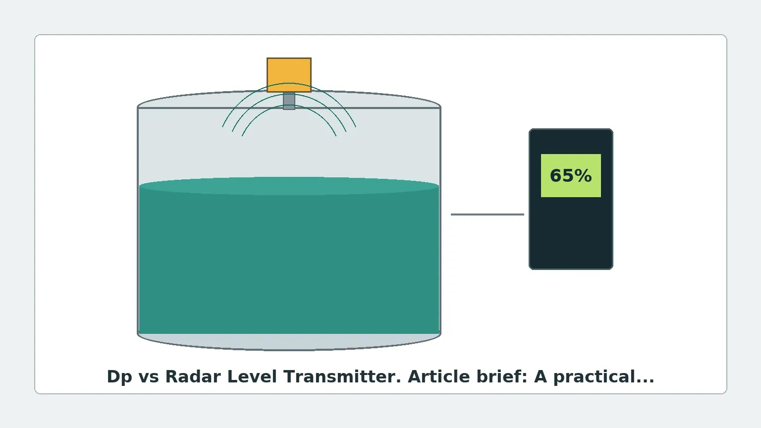
Radar level transmitters are non-contact instruments that use electromagnetic waves, typically in the microwave spectrum (6 GHz to 80 GHz). There are two primary types: Pulse Radar and Frequency Modulated Continuous Wave (FMCW) radar.
In both cases, the device emits a signal from the top of the tank toward the liquid surface. The signal reflects off the surface and returns to the sensor. The transmitter calculates the distance based on the Time-of-Flight (ToF).
Distance = (Speed of Light × Time) / 2
The level is then determined by subtracting the measured distance from the total tank height. Unlike DP, radar is largely independent of the liquid's density but is dependent on the material's dielectric constant (εr).
2. Technical Comparison: Dp vs Radar Level Transmitter
When evaluating a dp vs radar level transmitter, engineers must weigh several technical factors. The following table summarizes the key differences:
| Feature | Differential Pressure (DP) | Radar Level Meter |
| :— | :— | :— |
| Measurement Type | Contact (Hydrostatic) | Non-contact (Microwave) |
| Primary Variable | Liquid Density & Pressure | Dielectric Constant & Distance |
| Accuracy | 0.075% to 0.1% of span | ±1 mm to ±5 mm |
| Installation | Bottom/Side of tank | Top of tank |
| Density Sensitivity | High (Requires constant density) | None |
| Foam Sensitivity | Low (Measures mass) | High (Can attenuate signal) |
| Moving Parts | None | None |
| Maintenance | High (Impulse lines/Seals) | Low (No contact) |
| Typical Cost | Moderate | Moderate to High |
3. Selection Criteria for Industrial Applications
Process Density Stability
The most significant limitation of DP transmitters is their reliance on constant liquid density. If the temperature of the process fluid fluctuates significantly, or if the composition of the fluid changes, the density (ρ) will change. Since the DP transmitter only measures pressure, it will interpret a density decrease as a level drop, leading to measurement errors. Radar, being a distance-based technology, is unaffected by density changes, making it superior for applications with varying temperatures or mixed chemical batches.
Media Properties: Dielectric Constant vs. Corrosivity
Radar performance depends on the dielectric constant of the medium. Materials with low dielectric constants (e.g., liquid nitrogen, certain hydrocarbons) reflect less energy, requiring high-sensitivity 80 GHz radar units.
Conversely, DP transmitters are often preferred for highly corrosive media where exotic materials (Hastelloy, Monel, or Tantalum) are required for the diaphragm. While radar is non-contact, the antenna still faces the process vapors. However, modern radar units often feature PTFE-encapsulated antennas to resist corrosion.
Tank Geometry and Obstructions
DP transmitters require process penetrations (taps) at the bottom and top of the vessel. This can be a disadvantage in lined tanks or high-pressure reactors where additional holes increase the risk of leaks.
Radar transmitters are installed at the top. While this simplifies installation in many cases, the engineer must ensure the radar beam has a clear "line of sight" to the liquid surface. Internal obstructions like agitators, heating coils, or baffles can create false echoes. Advanced signal processing and "false echo suppression" software in modern Radar Level Meters help mitigate these issues.
4. Installation Considerations and Constraints
DP Transmitter Installation
1. Impulse Piping: Traditional DP setups use small-bore impulse lines to connect the process to the transmitter. These lines are prone to clogging, freezing, or trapping gas bubbles, which can cause significant measurement drift.
2. Diaphragm Seals: To avoid impulse line issues, many engineers specify capillary-based diaphragm seals. While more reliable, these are sensitive to ambient temperature fluctuations affecting the fill fluid.
3. Zero Calibration: DP transmitters must be zeroed at the specific installation height to account for the weight of the liquid in the impulse lines or capillaries.
Radar Transmitter Installation
1. Nozzle Dynamics: The height and diameter of the mounting nozzle can affect the radar signal. A nozzle that is too long or too narrow can cause "ringing" or internal reflections.
2. Dead Zones: Every radar has a "near-zone" or blocking distance (typically 50 mm to 300 mm from the flange) where measurement is not possible. This must be considered when the tank is filled to 100% capacity.
3. Beam Angle: Higher frequency radars (e.g., 80 GHz) have narrower beam angles (as low as 3°), allowing them to be installed closer to tank walls or in tanks with internal obstructions without interference.
5. Application Risks and Limitations
When to Avoid DP Transmitters
* Vacuum Service: In high-vacuum applications, the fill fluid in diaphragm seals can outgas, causing the diaphragm to "balloon" and fail.
* Varying Density: Processes involving blending or wide temperature swings will result in inaccurate level data unless density compensation is integrated into the control system.
When to Avoid Radar Transmitters
* Heavy Foam: Thick, dense foam can absorb or scatter microwave signals, leading to a "loss of echo." In such cases, Guided Wave Radar (GWR) or DP may be more appropriate.
* Extremely Low Dielectric Media: If the εr is below 1.4, standard pulse radar may struggle to detect the surface without a stilling well.
6. Maintenance and Lifecycle Costs
From an Operational Expenditure (OPEX) perspective, the dp vs radar level transmitter debate often favors radar. Because radar is a non-contact technology, there are no mechanical parts or diaphragms in direct contact with the liquid (in most configurations). This reduces the wear and tear caused by abrasive or corrosive fluids.
DP transmitters, particularly those using impulse lines, require periodic "blowing down" or cleaning to prevent blockages. Diaphragm seals are also susceptible to mechanical damage during tank cleaning or due to pressure spikes. However, DP transmitters are generally easier to calibrate in the field using a handheld pressure pump, whereas radar calibration often requires specialized software or manufacturer-specific communicators.
7. Specification Checklist for International Buyers
When sourcing level instrumentation for industrial projects, technical buyers should confirm the following parameters with the manufacturer:
1. Process Media Details: Name, concentration, density range, and dielectric constant.
2. Operating Conditions: Normal and maximum pressure (bar/MPa) and temperature (°C).
3. Vessel Specifications: Total height, diameter, material of construction, and presence of agitators.
4. Connection Requirements: Flange size and rating (e.g., DN50 PN40 or 2" ANSI 150#) or thread type.
5. Output and Communication: 4-20mA HART, Modbus RS485, or Profibus.
6. Certifications: Explosion-proof (ATEX/IECEx) requirements and SIL (Safety Integrity Level) ratings for safety instrumented systems.
8. Frequently Asked Questions (FAQs)
Q: Can a DP transmitter be used for solids level measurement?
No. DP transmitters rely on hydrostatic pressure, which is only applicable to liquids and gases. For solids, radar level meters or ultrasonic sensors are required.
Q: Is radar always more accurate than DP?
In terms of linear distance, radar is often more accurate (±1-3 mm). However, if the goal is to measure the mass or weight of the liquid in the tank, a DP transmitter is inherently more accurate because it measures pressure (force/area), which relates directly to mass regardless of volume expansion.
Q: How does turbulence affect these transmitters?
Turbulence can cause the liquid surface to fluctuate. Radar transmitters use damping algorithms to average these fluctuations. DP transmitters are less affected by surface turbulence but can be affected by the rapid pressure changes caused by high-speed agitators.
Q: What is the impact of steam or vapor on measurement?
High-pressure steam can slow down the speed of microwave signals in radar measurement, leading to a small error (typically less than 1%). DP transmitters are unaffected by the vapor space composition as long as the low-pressure side is properly compensated.
Conclusion
The choice between a dp vs radar level transmitter is not about which technology is "better," but which is better suited for the specific application. DP transmitters remain the standard for high-pressure mass-based measurements and applications where density is constant. However, the falling cost and increasing reliability of non-contact Radar Level Meters have made them the preferred choice for most modern industrial level applications, particularly where density fluctuations and maintenance reduction are priorities.
For complex installations, engineers should perform a site-specific review of the vessel and process conditions to ensure the selected instrument provides the required accuracy and longevity.