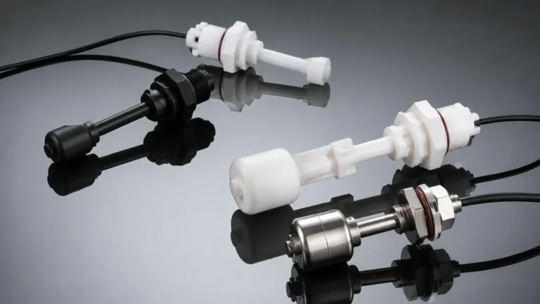
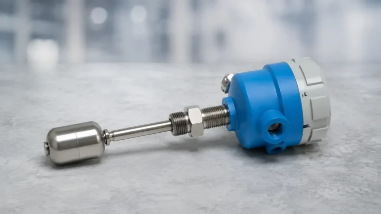
Displacer Level Switches
Displacer Level Switches
In the landscape of industrial process control, the ability to detect specific liquid levels reliably is critical for safety, inventory management, and operational efficiency. Among the diverse array of Level Switches available to engineers, displacer level switches occupy a unique niche. Known for their robustness in high-pressure environments and their ability to handle turbulent surfaces, these instruments rely on fundamental physics to provide point-level detection in tanks, boilers, and sumps.
This guide examines the mechanical principles, selection criteria, and installation requirements for displacer level switches, providing a technical reference for engineers and plant operators.
Understanding the Measurement Principle
Displacer level switches operate based on Archimedes' Principle, which states that a body immersed in a fluid is buoyed up by a force equal to the weight of the fluid displaced by the body. Unlike a standard float switch, which is designed to be lighter than the liquid and stay on the surface, a displacer is intentionally designed to be heavier than the liquid it is measuring.
The Force Balance Mechanism
The operation of a displacer switch involves three primary components: the displacer (usually a weighted cylinder), a high-tension spring, and an attraction sleeve or rod connected to a switching mechanism.
1. Dry State: When the liquid level is below the displacer, the full weight of the displacer pulls on the spring. In this state, the spring is extended, and the switching mechanism remains in its "normal" position.
2. Rising Level: As the liquid rises and begins to submerge the displacer, the displacer experiences an upward buoyant force. This force is proportional to the volume of the liquid displaced.
3. Actuation: The buoyant force reduces the effective weight (apparent weight) of the displacer. This reduction in weight allows the spring to retract. As the spring moves upward, it brings an attraction sleeve into the field of a permanent magnet located outside the pressure boundary. This magnetic coupling triggers the switch contact (SPDT or DPDT).
Because the displacer does not need to float, it can be made of heavy-duty materials like Stainless Steel 316, Monel, or Hastelloy, making it suitable for high-density liquids and high-pressure vessels where thin-walled floats might collapse.
Key Design Variations
Displacer level switches are engineered in several configurations to suit different vessel geometries and process conditions. Understanding these variations is essential for correct application.
Single-Stage vs. Multi-Stage Switches
A single-stage switch monitors a single set point (High or Low). However, one of the primary advantages of displacer technology is the ability to support multiple set points on a single instrument. By hanging multiple displacers at different heights on a single cable or rod, a single switch housing can provide High-High, High, Low, and Low-Low level alarms. This reduces the number of vessel penetrations required.
Top-Mounted vs. External Cage
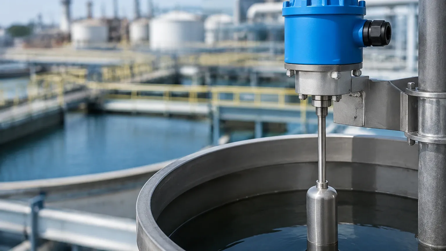
* Top-Mounted: These are installed directly through a flange on the top of the tank. They are ideal for sumps and open reservoirs. The displacer is suspended on a cable or rod that can extend several meters into the tank.
* External Cage: In high-pressure or high-temperature applications, such as steam boilers or refinery towers, the switch is often mounted in an external chamber (cage) piped to the side of the vessel. This allows the instrument to be isolated for maintenance without draining the main tank and provides a calmer environment for measurement if the main vessel is agitated.
Technical Selection Criteria
Selecting the correct displacer level switch requires a detailed analysis of the process media and the vessel environment. The following table outlines the primary factors to consider:
| Parameter | Consideration | Engineering Impact |
| :— | :— | :— |
| Specific Gravity (SG) | Range typically 0.40 to 2.40 | The displacer weight and spring tension must be calibrated to the liquid's density to ensure the buoyant force is sufficient to trigger the switch. |
| Operating Pressure | Up to 345 bar (5000 psi) | Higher pressures require thicker-walled external cages and robust sealing interfaces. |
| Operating Temperature | -196°C to +540°C (-320°F to +1000°F) | Extreme temperatures require cooling fins or heaters for the switch housing to protect the electrical components. |
| Liquid Viscosity | Maximum 1500 cP | Highly viscous or "sticky" liquids can impede the movement of the displacer or coat the cable, leading to delayed response or failure. |
| Interface Detection | Density difference > 0.1 SG | Displacers can be calibrated to detect the interface between two immiscible liquids (e.g., oil and water). |
Material Compatibility
Welk and other manufacturers offer various materials for the wetted parts. While Stainless Steel 316 is the standard, aggressive chemical environments may require:
* Hastelloy C: For high-corrosion chemical processing.
* Monel: For hydrofluoric acid or seawater applications.
* PTFE Coating: To prevent buildup on the displacer in scaling or crystallization applications.
Installation and Maintenance Considerations
To ensure the longevity and accuracy of displacer level switches, specific installation protocols must be followed.
Orientation and Clearance
For top-mounted units, the displacer must hang perfectly vertical. If the displacer hits the side of a nozzle or a tank internal (like an agitator or baffle), the friction will prevent the spring from retracting correctly. A minimum clearance of 25mm (1 inch) around the displacer is generally recommended. In deep tanks with high flow rates, a stilling well (a perforated pipe) should be used to prevent the displacer from swinging.
External Cage Piping
When using an external cage, the piping should be as short and direct as possible. Use 1-inch or 2-inch NPT or flanged connections. It is a best practice to install isolation valves and a drain valve on the cage. This allows the operator to perform a "blow-down" to clear sediment and to test the switch by manually filling the cage with liquid.
Calibration and Specific Gravity Adjustments
Displacer switches are factory-calibrated for a specific liquid density. If the process liquid changes (e.g., switching from water to a light hydrocarbon), the switch may not actuate at the correct level. Most industrial units allow for field adjustment of the spring tension or the position of the attraction sleeve to compensate for minor SG variations.
Limitations and Application Constraints
While displacer level switches are highly versatile, they are not universal solutions. Engineers should be aware of the following limitations:
1. Density Sensitivity: Because the principle is weight-based, significant fluctuations in liquid density (caused by temperature swings or concentration changes) will shift the actuation point. If the density drops below the design minimum, the switch may fail to reset.
2. Mechanical Wear: As a mechanical device with moving parts (the spring and sleeve), it is subject to fatigue over millions of cycles. Regular inspection of the spring for corrosion or loss of tension is necessary.
3. Coating and Scaling: If the process liquid leaves heavy deposits on the displacer, the added weight will change the calibration. In such cases, non-contact technologies like radar or ultrasonic sensors may be preferable, although they lack the inherent mechanical simplicity of the displacer.
4. Turbulence: While better than floats, extreme turbulence can still cause "chatter" in the switch contacts. Using a stilling well or a switch with a built-in time delay can mitigate this.
Comparison with Other Level Switch Technologies
| Technology | Advantage | Disadvantage |
| :— | :— | :— |
| Displacer | High pressure/temp, stable in turbulence, multiple set points. | Density dependent, mechanical wear. |
| Float Switch | Low cost, simple installation. | Limited pressure rating, prone to sinking if punctured. |
| Ultrasonic | Non-contact, no moving parts. | Sensitive to foam, vapor, and vacuum. |
| Vibrating Fork | Not density dependent, compact. | Subject to coating, single set point only. |
Frequently Asked Questions (FAQ)
Q: Can a displacer level switch be used for interface measurement?
A: Yes. By weighting the displacer so that it is heavier than the upper liquid but lighter than the lower liquid (relative to the displaced volume), the switch will only actuate when the interface level reaches the displacer.
Q: What is the maximum length for a displacer suspension?
A: For top-mounted units using a cable suspension, lengths of up to 15 meters (approx. 50 feet) are possible, though intermediate guides may be required to prevent swaying.
Q: How do I test the switch without filling the tank?
A: For external cage models, you can close the isolation valves and fill the cage with a test fluid or use the drain valve to lower the level. For top-mounted units, some designs include a "test lifting lever" that allows an operator to manually lift the internal rod to simulate a high-level condition.
Q: Does the displacer need to be fully submerged to work?
A: Not necessarily. The switch is calibrated to actuate when a specific portion of the displacer is submerged. This "immersion depth" provides the necessary buoyant force to overcome the spring tension.
Conclusion
Displacer level switches remain a cornerstone of industrial level control due to their mechanical simplicity and reliability in extreme process conditions. By understanding the buoyancy physics and the specific gravity requirements of the media, engineers can implement these devices to provide fail-safe high and low-level protection. For complex applications involving high-pressure steam or hazardous chemicals, consulting with a manufacturer like Welk ensures that the materials and spring rates are precisely matched to the operational environment.
For more detailed specifications on various point-level technologies, including magnetic and mechanical options, you can Review product options and application support to find the optimal solution for your facility's requirements.