Level Switch with Indicator
Level Switch with Indicator
In industrial process control, point level detection serves as a critical safeguard against tank overfills, dry-run conditions in pumps, and inventory inaccuracies. While a standard level switch is designed to transmit a discrete signal to a Programmable Logic Controller (PLC) or Distributed Control System (DCS), the integration of a local visual signal transforms the device into a level switch with indicator. This dual-functionality provides onsite operators with immediate, real-time status updates without requiring access to a control room, enhancing both safety and operational efficiency.
Selecting the right Level Switches involves understanding the underlying physics of the sensor and the specific environmental requirements of the application. This guide explores the measurement principles, selection criteria, and practical installation considerations for level switches equipped with local indicators.
Measurement Principles for Point Level Detection
Before selecting a level switch with indicator, it is essential to understand how different sensing technologies interact with the medium. Each principle offers distinct advantages depending on the physical properties of the liquid or solid being measured.
1. Vibrating Fork (Tuning Fork) Technology
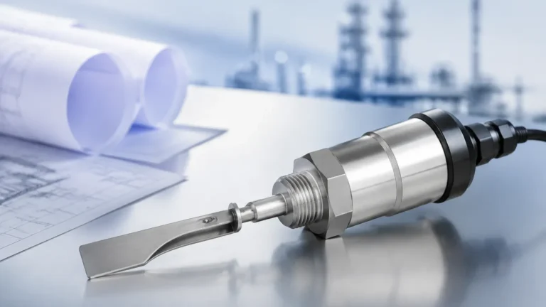
The vibrating fork level switch utilizes a piezoelectric crystal to energize a tuning fork at its natural resonance frequency (typically around 1,200 Hz to 1,400 Hz). When the fork is immersed in a liquid or solid, the frequency shifts or the amplitude of vibration is dampened. The internal electronics detect this change and trigger the switch output.
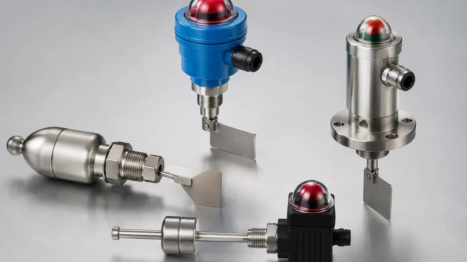
In models featuring an indicator, a high-intensity LED ring or a localized lamp assembly usually changes color (e.g., from green to red) to signify the change in state. This technology is highly reliable as it is largely unaffected by turbulence, bubbles, or foam.
2. Capacitance Level Sensing
Capacitance switches treat the sensor probe and the tank wall (or a reference probe) as two plates of a capacitor. The medium acts as the dielectric material. As the level rises and covers the probe, the capacitance value changes because the dielectric constant of the medium (such as water or oil) is significantly higher than that of air.
A level switch with indicator using capacitance often includes a small digital display or a bar graph. This is particularly useful for detecting interfaces between two different liquids or for media that may leave a coating on the probe, as the indicator can show the "approach" to a switch point.
3. Float and Magnetic Principles
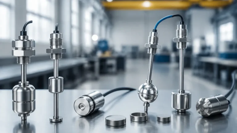
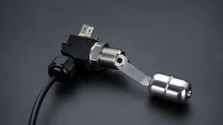
Float switches rely on buoyancy. A float containing a permanent magnet moves with the liquid level along a stem. Inside the stem, a reed switch or a Hall-effect sensor is triggered when the magnet reaches a specific position.
For these mechanical systems, the "indicator" can be a physical flag (common in magnetic level gauges) or an integrated LED housed in the junction box. These are frequently used in water treatment and fuel storage due to their simplicity and low power consumption.
4. Ultrasonic Point Level Detection
Ultrasonic switches use a pair of piezoelectric crystals separated by a small gap. One crystal emits an ultrasonic pulse, and the other receives it. When the gap is filled with liquid, the pulse travels across; when air is present, the pulse is attenuated. A level switch with indicator in this category often uses diagnostic LEDs to show signal strength, helping operators verify that the sensor is not fouled by debris.
The Role of the Local Indicator
The primary purpose of an indicator on a level switch is to provide "at-a-glance" verification. In large-scale industrial plants, the distance between the sensor and the control room can be hundreds of meters. A local indicator serves several functions:
* Commissioning Support: During installation, the indicator allows the technician to verify the switch point immediately by manually raising the level or simulating the media presence.
* Maintenance Diagnostics: Many modern indicators use flash patterns to indicate specific errors, such as a short circuit, sensor fouling, or supply voltage drops.
* Safety Redundancy: If the communication line to the PLC fails, the local indicator remains a reliable source of truth for operators performing manual tank filling or emptying.
Technical Comparison and Selection Table
Choosing the correct technology requires a balance between media characteristics and the required visibility of the indicator. The following table provides a general reference for common industrial scenarios.
| Technology | Suitable Media | Indicator Type | Typical Accuracy | Pressure/Temp Limits |
| :— | :— | :— | :— | :— |
| Vibrating Fork | Liquids, Powders, Granules | LED Ring (360° Visibility) | ±1 mm | Up to 64 bar / 150°C |
| Capacitance | Acids, Slurries, Pastes | Digital OLED / LED Bar | ±2 mm | Up to 100 bar / 200°C |
| Float Switch | Clean Liquids, Oils | LED Lamp / Mechanical Flag | ±5 mm | Up to 40 bar / 120°C |
| Ultrasonic | Non-foaming Liquids | Status LED | ±2 mm | Up to 10 bar / 80°C |
| Conductive | Conductive Liquids (Water) | Multi-color LED | ±3 mm | Up to 20 bar / 100°C |
Key Evaluation Criteria for B2B Procurement
When specifying a level switch with indicator for a project, engineers must confirm several technical parameters to ensure long-term reliability.
Media Compatibility
The wetted parts (the parts of the sensor in contact with the material) must be chemically compatible. Stainless steel (316L) is the industry standard, but for highly corrosive environments, coatings like PTFE (Teflon) or PFA are necessary. The indicator housing itself should be resistant to the ambient atmosphere, especially in chemical processing plants.
Visibility and Environment
If the switch is installed outdoors in direct sunlight, a standard low-intensity LED may be invisible. High-brightness LEDs or shrouded displays are required. Conversely, in hazardous areas, the indicator must be housed in an explosion-proof (Ex d) or intrinsically safe (Ex i) enclosure, which may limit the type of display used.
Output Options
While the indicator provides local data, the switch must still communicate with the broader system. Common outputs include:
* Relay (SPDT/DPDT): For direct control of pumps or valves.
* PNP/NPN: For high-speed digital input to a PLC.
* Two-wire (8/16mA): For loop-powered systems where the current level indicates the switch state.
Installation and Maintenance Considerations
Proper installation is paramount to the functionality of the indicator and the sensor's accuracy.
1. Orientation: For vibrating forks, the tines should be oriented so that liquid can easily drain off them. If installed horizontally, the tines should be vertical (side-by-side) to prevent material buildup between them.
2. Visual Access: Ensure the indicator is oriented toward the walkway or access platform. Many level switches allow the housing to be rotated 300° to 360° after threading it into the process connection to optimize visibility.
3. Cable Entry: Always use a drip loop in the cabling to prevent moisture from entering the housing via the cable gland. Moisture ingress is the leading cause of indicator failure in humid or outdoor environments.
4. Calibration: While many point level switches are "plug-and-play," capacitance and ultrasonic models may require a sensitivity adjustment. The local indicator often provides feedback during this process, showing when the "trip point" has been reached.
Limitations of Level Switches with Indicators
Despite their utility, there are constraints to consider:
* Localized Benefit: An indicator is only useful if a human is present to see it. It does not replace the need for remote monitoring in automated facilities.
* Power Constraints: High-visibility indicators require more power. In strictly battery-powered or ultra-low-power wireless applications, the indicator may be programmed to remain off unless a button is pressed.
* Coating Issues: If the media is highly viscous or prone to crystallization, it can coat the sensor. While the indicator might show a "high" state, it could be a false positive. In such cases, vibrating forks with "coating rejection" logic are preferred.
Frequently Asked Questions (FAQ)
Q: Can a level switch with indicator be used for continuous level measurement?
A: No. A level switch is a point-level device (On/Off). If you need to know the exact percentage of a tank's volume (e.g., 45% full), you require a level transmitter, which may also feature a local indicator or display.
Q: What is the difference between an LED ring and a standard LED pilot light?
A: An LED ring is typically integrated into the body of the sensor and provides 360-degree visibility. This is superior in complex pipework where a standard pilot light might be hidden from certain angles.
Q: Are these devices suitable for high-vibration environments?
A: Yes, provided you select a solid-state technology like a vibrating fork or capacitance switch. Mechanical float switches are prone to false triggering or mechanical failure in high-vibration settings (e.g., near large compressors).
Q: How do I verify the indicator is working correctly?
A: Most high-quality level switches include a "test" function. This can be a magnetic test point on the outside of the housing or a button that, when pressed, forces the switch and the indicator to change state, verifying the electronics and the visual output.
For engineers and procurement managers, selecting a level switch with indicator ensures that the first line of defense in level control is both electronically sound and human-readable. By matching the measurement principle to the media and ensuring the indicator is visible and robust, facilities can significantly reduce the risk of undetected process excursions.