Hydrostatic Level Switches
Hydrostatic Level Switches
In industrial process control, the ability to detect specific liquid levels reliably is fundamental to safety, inventory management, and automation. While many engineers are familiar with mechanical float switches or ultrasonic sensors, hydrostatic level switches offer a robust, solid-state alternative that excels in challenging environments. By utilizing the physical relationship between liquid height and pressure, these devices provide high-precision point level detection without the maintenance requirements of moving parts.
As a professional manufacturer, Welk specializes in providing advanced Level Switches and measurement instruments tailored for water treatment, chemical processing, and industrial automation. Understanding the underlying physics and selection criteria of hydrostatic technology is essential for ensuring long-term operational stability.
The Principle of Hydrostatic Level Measurement
The operation of hydrostatic level switches is based on Pascal’s Law, which states that the pressure exerted by a static liquid at a specific depth is directly proportional to the height of the liquid column above it, provided the density of the liquid remains constant.
The mathematical formula used to determine the level is:
P = ρ × g × h
Where:
* P is the hydrostatic pressure (measured in Pascals or bar).
* ρ (rho) is the density of the liquid (kg/m³).
* g is the acceleration due to gravity (approximately 9.81 m/s²).
* h is the height of the liquid column (meters).
In a hydrostatic level switch, a sensitive diaphragm—typically made of stainless steel, ceramic, or Hastelloy—deforms slightly under the weight of the liquid. This physical deformation is converted into an electrical signal by a piezoresistive or capacitive sensing element. Once the pressure reaches a pre-defined threshold (the setpoint), the internal electronics trigger a switching output, such as a relay or a transistor (PNP/NPN), to signal that the liquid has reached a specific high or low level.
Atmospheric Pressure Compensation
Because the sensor is measuring the pressure exerted by the liquid, it must also account for the atmospheric pressure acting on the surface of the liquid in an open tank. To ensure accuracy, hydrostatic level switches are typically "vented." This is achieved through a small capillary tube within the sensor cable or a vent on the housing, which allows the sensor to reference the current atmospheric pressure. This ensures that the switch only reacts to the pressure generated by the liquid height, rather than changes in weather or altitude.
Why Choose Hydrostatic Technology for Point Level Control?
Hydrostatic level switches are often preferred over mechanical or optical alternatives in specific B2B applications due to their durability and lack of moving components.
1. Immunity to Surface Conditions: Unlike ultrasonic or radar sensors, hydrostatic switches are not affected by surface foam, dust, or vapors. Since they measure the mass of the liquid at the bottom of the tank, the state of the liquid's surface is irrelevant.
2. No Moving Parts: Mechanical float switches are prone to jamming, scaling, or mechanical fatigue. Hydrostatic sensors are solid-state, significantly reducing the risk of failure in viscous or debris-laden liquids.
3. High Pressure and Temperature Resistance: High-quality hydrostatic switches can be engineered to withstand significant process pressures and temperatures that would destroy standard plastic sensors.
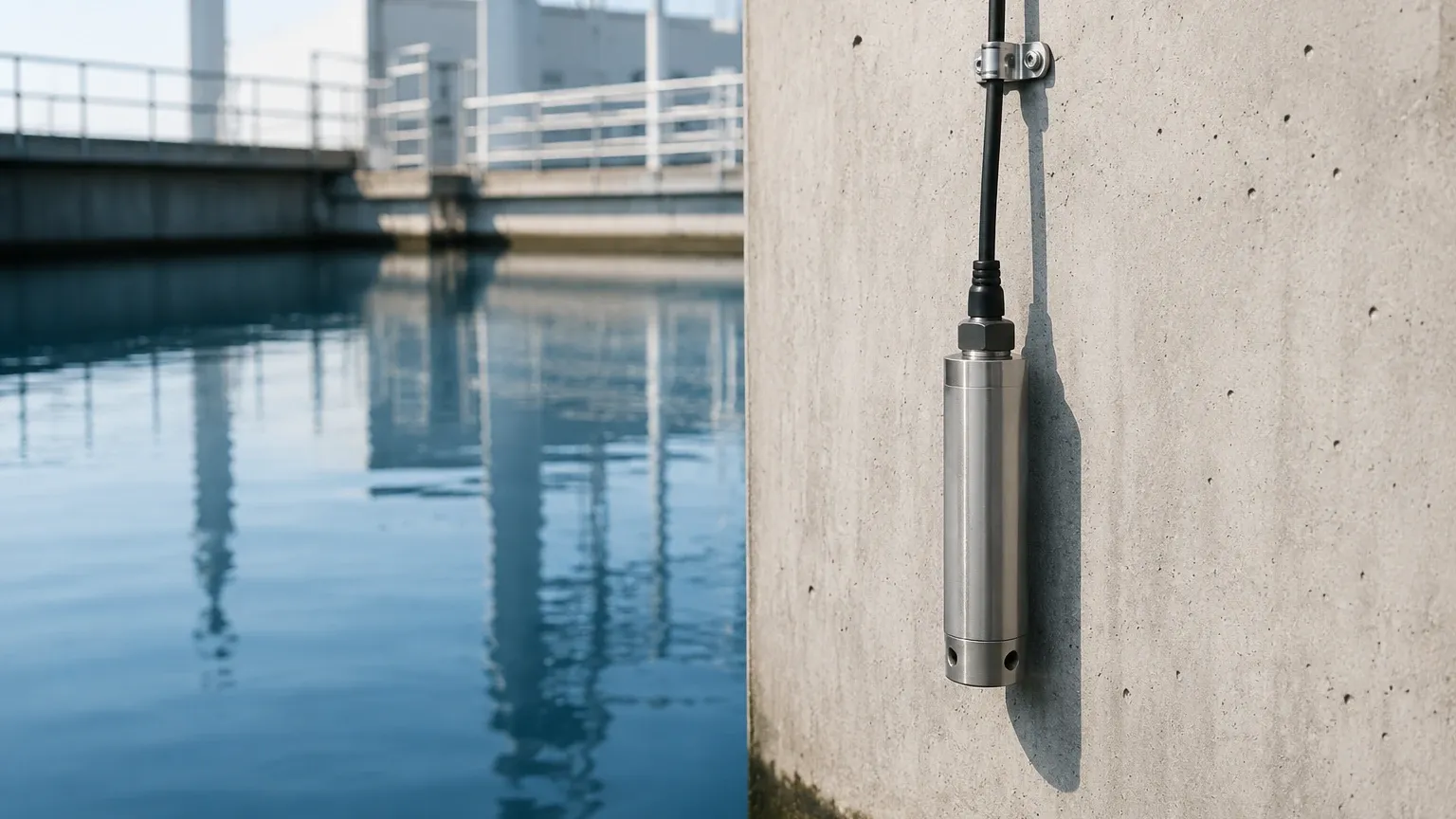
4. Versatility in Mounting: They can be mounted at the bottom of a tank via a threaded connection or submerged directly into a well or reservoir using a reinforced cable.
Key Evaluation Criteria for Selection
Selecting the correct hydrostatic level switches requires a detailed understanding of the process environment. Engineers should evaluate the following criteria before procurement:
1. Media Density (Specific Gravity)
Since the switch operates based on weight, any change in the liquid’s density will change the switch point. If a tank is used for different chemicals with varying densities, a hydrostatic switch may require recalibration for each medium. It is vital to confirm the specific gravity (SG) of the liquid during the design phase.
2. Chemical Compatibility
The wetted parts—the diaphragm and the housing—must be compatible with the process media.
* Stainless Steel (316L): Standard for water and mild chemicals.
* Ceramic: Highly resistant to abrasion and many corrosive acids.
* PTFE/FEP Coatings: Used for extremely aggressive chemical applications to prevent corrosion of the sensor body or cable.
3. Measuring Range and Setpoints
While these are point level switches, the sensor must be rated for the maximum possible pressure (depth) of the tank to prevent diaphragm damage. Users should define whether they require a fixed setpoint or an adjustable one that can be programmed via a display or a digital interface.
4. Output Configuration
Depending on the control system (PLC or DCS), the switch should provide an appropriate output. Common options include:
* Relay Outputs (SPDT): For direct control of pumps or alarms.
* Transistor Outputs (PNP/NPN): For high-speed switching in automation circuits.
* IO-Link: For modern "Industry 4.0" integration, providing diagnostic data alongside the switch status.
Practical Selection Table
| Feature | Submersible Hydrostatic Switch | Externally Mounted Pressure Switch |
| :— | :— | :— |
| Installation | Dropped into the tank/well via cable | Threaded or flanged to the tank wall |
| Best For | Deep wells, reservoirs, open sumps | Process tanks, pressurized vessels |
| Maintenance | Easy to pull up for cleaning | May require tank drainage to remove |
| Venting | Integrated capillary tube in cable | Venting on the sensor housing |
| Max Depth | Up to 200m or more | Limited by tank height/nozzle position |
Installation Considerations and Best Practices
Proper installation is critical to the longevity and accuracy of hydrostatic level switches. Failure to follow engineering guidelines can lead to premature sensor failure or false triggering.
* Avoid Turbulence: Do not install the sensor directly near a liquid inlet or an agitator. The kinetic energy of moving water can create localized pressure fluctuations, leading to "chatter" or false switching. If turbulence is unavoidable, use a stilling well (a perforated pipe) to protect the sensor.
* Moisture Protection for Vent Tubes: For submersible models, the vent tube in the cable must remain unobstructed and protected from moisture. If water enters the vent tube, it can damage the internal electronics and cause measurement drift. Using a desiccant filter at the end of the vent tube is highly recommended in humid environments.
* Sediment and Sludge: In wastewater or mining applications, sediment can accumulate at the bottom of the tank. Mount the sensor slightly above the expected sludge level to prevent the diaphragm from becoming buried, which would result in inaccurate pressure readings.
* Cable Securing: For deep submersible applications, ensure the cable is properly supported by a strain-relief clamp. The weight of a long cable can stretch the internal wires or the vent tube over time if not correctly anchored.
Limitations and Common Risks
While hydrostatic level switches are highly reliable, they are not universal solutions. Engineers must be aware of the following limitations:
* Pressurized Tanks: In a closed, pressurized vessel, the sensor will measure both the liquid head pressure and the gas blanket pressure. To use hydrostatic switching in this environment, a differential pressure setup is required to subtract the gas pressure from the total pressure.
* Temperature-Induced Density Changes: If the process temperature fluctuates significantly, the density of the liquid may change. Because hydrostatic pressure depends on density, the actual liquid level at which the switch triggers may shift slightly as the liquid heats or cools.
* Diaphragm Fragility: The sensing diaphragm is a precision component. It should never be touched or cleaned with sharp objects, as even a small dent can ruin the calibration or puncture the seal.
Frequently Asked Questions (FAQs)
Q: Can hydrostatic level switches be used in boiling liquids?
A: It is generally not recommended. Boiling creates significant turbulence and bubbles (gas pockets) within the liquid, which changes the effective density and creates erratic pressure readings. High-temperature versions exist, but they are typically used for hot, stable liquids rather than actively boiling ones.
Q: How do I test the switch without filling the tank?
A: Many modern hydrostatic switches from Welk feature a test button or a digital interface that allows you to simulate a high-pressure condition to verify that the relay or transistor output is functioning correctly. Alternatively, a pressure calibrator can be used on externally mounted units.
Q: Is a hydrostatic switch affected by the dielectric constant of the liquid?
A: No. Unlike capacitive or radar-based level switches, hydrostatic sensors are purely mechanical/pressure-based. They work perfectly regardless of whether the liquid is conductive, non-conductive, or has a high or low dielectric constant.
Q: How often should these sensors be calibrated?
A: In stable, clean water applications, hydrostatic switches can operate for years without recalibration. However, in corrosive chemical applications or those with high particulate matter, an annual calibration check is recommended to ensure the diaphragm has not suffered from coating or degradation.
For engineers seeking a balance between cost-effectiveness and industrial-grade reliability, hydrostatic level switches represent a premier choice for point level detection. By eliminating moving parts and focusing on the fundamental physics of pressure, these devices ensure that critical processes remain within their defined operational boundaries.
To explore specific configurations for your application, you can Review product options and application support to find the ideal solution for your facility's requirements.