Switches Standard Dimensions from Floor Level
Switches Standard Dimensions from Floor Level
In industrial automation and process control, the positioning of instrumentation is as critical as the technology itself. When discussing switches standard dimensions from floor level, engineers must account for two distinct but related requirements: the ergonomic accessibility for operators and the technical positioning of sensors relative to the process media. For industrial facilities utilizing Level Switches, adhering to standardized mounting heights ensures safety, compliance with international accessibility codes, and long-term maintenance efficiency.
This guide explores the standard dimensions for mounting switches, the principles governing level switch installation, and how to select the appropriate technology based on spatial constraints and process requirements.
Understanding Level Switch Measurement Principles
Before determining the mounting height or the distance of a switch from the floor level, it is essential to understand how different level switches interact with the medium. Welk provides several technologies, each with specific installation footprints.
Float Level Switches
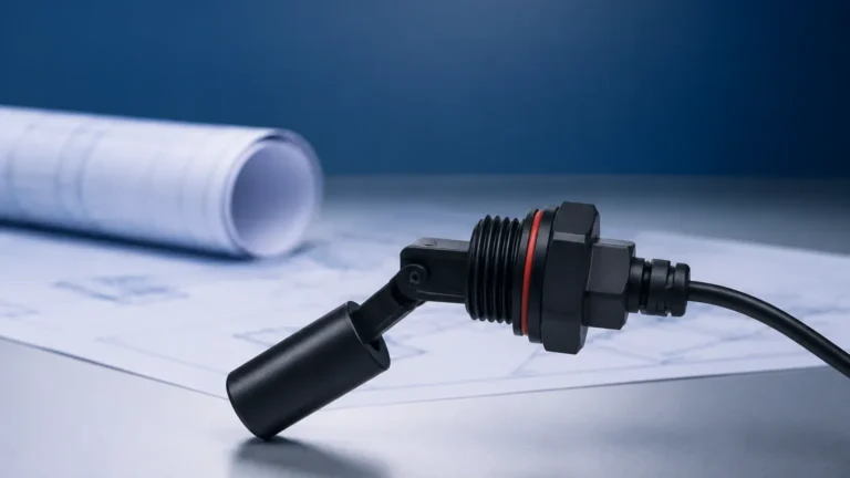
Float switches operate on the principle of buoyancy. A magnetic float moves with the liquid level, actuating a reed switch within the stem. These are often used in sumps and tanks where the "floor level" refers to the bottom of the vessel. The dimension from the floor is critical here to prevent the float from bottoming out or getting stuck in sediment.
Tuning Fork Level Switches
Tuning fork sensors utilize piezo-electric crystals to vibrate a fork at its natural frequency. When the fork is submerged in liquid or solids, the frequency changes, triggering the switch. These are frequently side-mounted. The dimension from the floor level to the mounting boss must be calculated to ensure the switch triggers at the exact high or low-level alarm point.
Capacitive Level Switches
These sensors measure the change in capacitance between the probe and the tank wall (or a reference electrode). They are highly versatile but require specific mounting clearances to avoid interference from the tank floor or internal structures.
Industry Standards for Switch Mounting Heights
When we refer to "switches standard dimensions from floor level" in a general industrial context, we often look at accessibility standards such as the Americans with Disabilities Act (ADA) or international ISO/IEC standards for human-machine interfaces (HMI).
Ergonomic and Accessibility Standards
For manual override switches, emergency stops, or local control panels associated with level instrumentation, the following dimensions are standard:
* Standard Mounting Height: Generally 1200 mm (approx. 48 inches) from the finished floor level to the center of the switch box.
* Minimum Height: 380 mm (15 inches) to avoid excessive bending.
* Maximum Height: 1220 mm (48 inches) for unobstructed reach, though some industrial standards allow up to 1400 mm (55 inches) for non-ADA compliant specialized zones.
Process-Specific Dimensions
In the context of level measurement, the "floor level" is often the bottom of a tank or a containment dike.
1. Low-Level Cutoff: Typically installed 100 mm to 300 mm (4 to 12 inches) above the tank floor to protect pumps from running dry while accounting for the "dead zone" at the bottom of the sensor.
2. Sump Pump Control: For basement or pit installations, the start switch is often set at 300 mm to 500 mm above the floor, with the stop switch at 100 mm.
Selection Table: Level Switch Types and Installation Characteristics
Choosing the right switch involves balancing the required detection point with the physical mounting constraints.
| Switch Type | Mounting Orientation | Typical Min. Distance from Floor | Ideal Application |
| :— | :— | :— | :— |
| Magnetic Float | Top or Side | 50 mm (2 inches) | Clean liquids, water treatment |
| Tuning Fork | Side or Top | 20 mm (0.8 inches) | Powders, granulates, liquids |
| Capacitive | Side | 30 mm (1.2 inches) | Corrosive chemicals, non-metallic tanks |
| Ultrasonic Gap | Side | 50 mm (2 inches) | Highly viscous liquids |
| Hydrostatic | Bottom/Submerged | 0 mm (Resting on floor) | Deep wells, open reservoirs |
Technical Considerations for Mounting Dimensions
When planning the installation of Level Switches, several technical dimensions must be verified to ensure the device functions within its design parameters.
The "Dead Zone" and Floor Clearance
Every level switch has a "dead zone"—a region where the sensor cannot accurately detect the medium. For a bottom-mounted or low-level side-mounted switch, the distance from the floor level must exceed this dead zone. For example, if a tuning fork switch has a 15 mm dead zone, mounting it 10 mm from the floor will result in a constant "tank empty" error or mechanical damage from sediment.
Nozzle and Flange Dimensions
For side-mounted switches, the standard dimension from the floor level is often dictated by the existing tank nozzles. Standard ANSI or DIN flanges usually require a minimum clearance of 150 mm (6 inches) from any weld seam or floor joint to ensure structural integrity and ease of bolting.
Cable Entry and Wiring Space
Standard dimensions must also account for the conduit or cable entry. A switch mounted too close to the floor (e.g., less than 200 mm) may not allow for the proper bending radius of armored cables or the installation of liquid-tight conduits, leading to premature cable failure or water ingress.

Installation Guidelines for Industrial Environments
To maintain compliance with switches standard dimensions from floor level and ensure operational reliability, follow these practical steps:
1. Verify the Finished Floor Level (FFL): In new constructions, the structural slab and the finished floor may differ by several centimeters. Always measure from the FFL to ensure ergonomic switches are at the correct height.
2. Account for Sedimentation: In wastewater or chemical processing, solids often settle at the bottom. Ensure that the lowest level switch is positioned at least 150 mm above the floor level to avoid false triggers caused by sludge buildup.
3. Avoid Turbulence Zones: Do not mount switches near floor-level inlets. The kinetic energy of incoming fluid can cause mechanical fatigue in float stems or vibration interference in tuning forks.
4. Orientation of the Conduit: Always ensure the conduit entry points downward or sideways. Even if the switch is at the standard height, a top-facing conduit entry will collect condensation and eventually short the switch.
Limitations and Common Risks
While following standard dimensions is recommended, certain process conditions require deviations:
* High-Vibration Areas: If the standard mounting height places the switch on a thin-walled section of a tank prone to vibration, a custom bracket or a different mounting height may be necessary to prevent sensor failure.
* Extreme Temperatures: In cryogenic or high-heat applications, the distance from the floor (or the tank wall) may need to be increased using extended necks to protect the electronics in the switch head from thermal damage.
* Coating and Scaling: In applications with calcium buildup or sticky resins, mounting a switch too close to the floor level increases the risk of the sensor being "buried" in deposits, regardless of the liquid level.
Frequently Asked Questions (FAQs)
What is the standard height for a manual reset switch on a boiler?
Typically, these are mounted between 1200 mm and 1400 mm from the floor level to ensure they are visible and accessible to the operator without the need for a ladder.
How far should a float switch be from the bottom of a sump?
To prevent the pump from sucking in air or debris, the "off" switch should be set so that the water level remains at least 100 mm to 150 mm above the floor of the sump.
Does the mounting height affect the accuracy of a level switch?
For point-level switches (on/off), the height determines the trigger point, not the accuracy. However, for hydrostatic level switches, the distance from the floor directly impacts the pressure reading, as it measures the liquid column above the sensor.
Are there specific dimensions for switches in hazardous areas (Ex zones)?
While the height dimensions remain similar for ergonomics, the clearance from the floor is often governed by the need to prevent the accumulation of heavy explosive gases, which may require the switch to be mounted higher or in a specifically ventilated area.
Conclusion
Adhering to switches standard dimensions from floor level is a fundamental aspect of industrial plant design. Whether it is ensuring that an operator can safely reach an emergency stop or positioning a tuning fork level switch to avoid sediment at the bottom of a vessel, these measurements dictate the safety and efficiency of the process. By combining ergonomic standards with the specific technical requirements of Welk's measurement technologies, engineers can create robust, compliant, and easy-to-maintain level control systems.
For more detailed specifications on mounting flanges, probe lengths, and housing options for your specific application, Review product options and application support to find the ideal solution for your facility.
Download Switches Standard Dimensions from Floor Level as a PDF