Level 2 and Level 3 Switches
Level 2 and Level 3 Switches
In the landscape of industrial automation and process control, the term "level switches" often bridges the gap between physical sensing and data-driven decision-making. While the terminology "level 2 and level 3 switches" frequently appears in networking contexts, in the realm of industrial level measurement, it refers to the integration of point-level sensors into the hierarchical layers of a manufacturing facility. Understanding how a physical level switch provides data to Level 2 (Control) and Level 3 (Operations Management) systems is essential for engineers designing reliable safety and inventory protocols.
Industrial level switches are binary sensors designed to detect the presence or absence of a medium at a specific height within a tank, silo, or pipe. These devices serve as the first line of defense against overfills and the primary indicator for dry-run protection. As manufacturing moves toward Industry 4.0, the role of Level Switches has evolved from simple local alarms to critical data points in the broader automation stack.
Measurement Principles of Modern Level Switches
Before selecting a switch for Level 2 or Level 3 integration, it is vital to understand the underlying physical principles that govern their operation. Different media—ranging from potable water to corrosive chemicals and dry powders—require specific sensing technologies to ensure accuracy and longevity.
Vibration (Tuning Fork) Principle
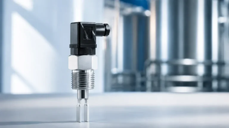
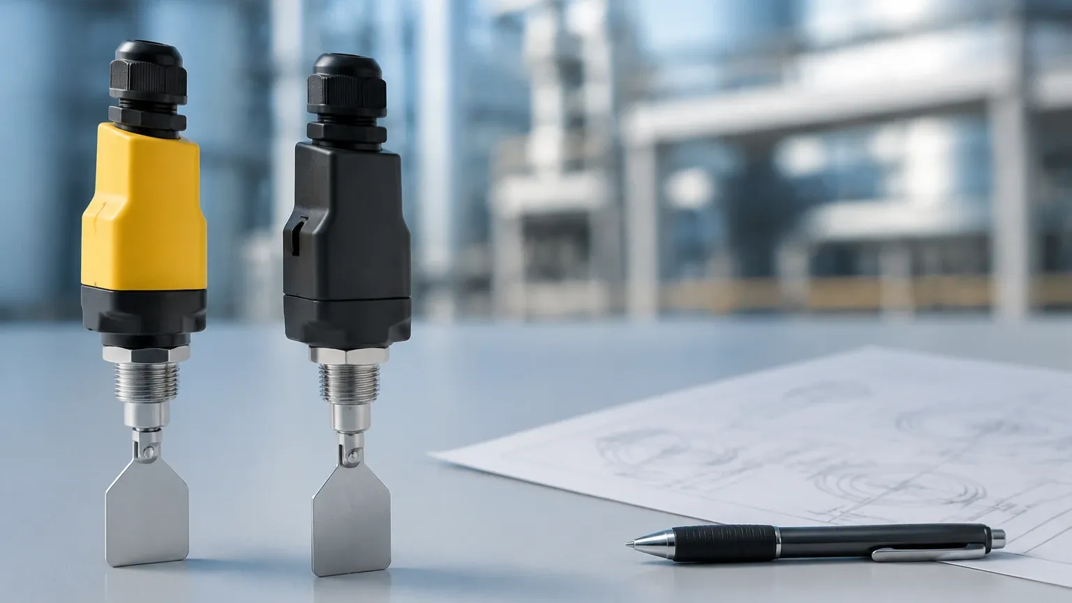
One of the most versatile technologies is the vibrating level switch, often called a tuning fork. The sensor's tines vibrate at their natural resonance frequency in the air. When the medium reaches the fork, the frequency drops due to the increased density of the surrounding material. An internal electronic circuit detects this shift and toggles the output state. This technology is highly resistant to changes in pressure, temperature, and foam.
Float and Magnetic Principle
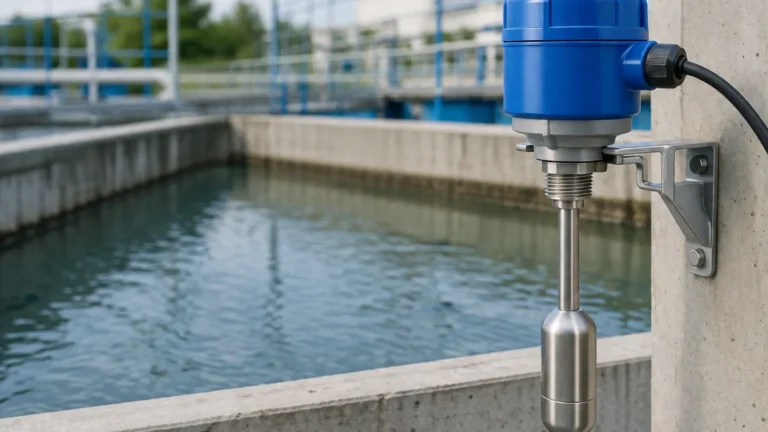
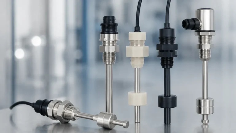
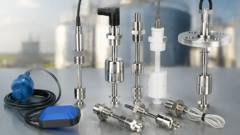
This is a mechanical approach where a float containing a magnet moves along a stem. As the liquid level rises, the float reaches a predetermined point where the magnetic field closes or opens a reed switch inside the stem. While simple and cost-effective, these are generally limited to clean, non-coating liquids to prevent mechanical sticking.
Capacitance Principle
Capacitive switches treat the sensor probe and the tank wall as two electrodes of a capacitor. The dielectric constant of the medium differs significantly from that of air. When the medium covers the probe, the capacitance increases, triggering the switch. These are excellent for detecting powders and granulates, though they may require calibration to account for material buildup on the probe.
Ultrasonic Point Level Detection
Ultrasonic switches use high-frequency sound waves. A transducer emits a pulse that travels through a gap in the sensor. If the gap is filled with liquid, the pulse reaches the receiver; if the gap is empty (filled with air or gas), the signal is attenuated. This non-contact or gap-sensing method is ideal for highly viscous liquids where mechanical parts would fail.
Integrating Level 2 and Level 3 Switches in Automation
To understand the application of level 2 and level 3 switches, one must look at the ISA-95 model, which defines the interface between enterprise and control systems.
Level 2: The Control Layer
In industrial architecture, Level 2 represents the human-machine interface (HMI) and supervisory control. A level switch at this stage is wired directly into a Programmable Logic Controller (PLC) or a Distributed Control System (DCS).
* Function: The switch provides real-time logic for pump control (start/stop) or valve actuation.
* Criticality: At Level 2, the switch is a safety component. For instance, if a high-level switch is triggered, the PLC immediately closes the inlet valve to prevent a spill.
* Connectivity: Most Level 2 switches use 2-wire or 3-wire DC signals (PNP/NPN) or relay contacts to communicate with the controller.
Level 3: The Operations Management Layer
Level 3 involves managing the production workflow, including inventory management, batch tracking, and maintenance scheduling.
* Function: Data from the level switches is aggregated to track how often a tank reaches its capacity or to calculate the total number of fill cycles for a specific period.
* Predictive Maintenance: By analyzing the response time and frequency of switch triggers at Level 3, engineers can predict when a sensor might be fouled or when a pump is underperforming.
* Inventory Reconciliation: While continuous level meters (like radar) provide volume data, level switches provide the "absolute zero" or "full" reference points used at the Level 3 management stage to calibrate inventory records.
Practical Selection Table for Industrial Applications
Choosing the right technology is the first step in ensuring reliable data for your Level 2 and Level 3 systems. The following table compares common technologies manufactured by Welk and other professional suppliers.
| Technology | Media Suitability | Pressure Range | Temperature Range | Best Use Case |
| :— | :— | :— | :— | :— |
| Vibrating Fork | Liquids & Solids | Up to 40 bar | -50°C to 150°C | Overfill protection in chemical tanks |
| Float Switch | Clean Liquids | Up to 20 bar | -20°C to 120°C | Water treatment and oil sumps |
| Capacitance | Powders/Granules | Up to 25 bar | -40°C to 200°C | Grain silos and cement storage |
| Ultrasonic | Viscous Liquids | Up to 10 bar | -40°C to 100°C | Lubricating oils and wastewater |
| Hydrostatic | Water/Slurry | N/A (Submersible) | 0°C to 80°C | Deep wells and open reservoirs |
Installation Considerations and Best Practices
Proper installation is paramount to preventing false positives in your Level 2 control loops. Even the most advanced Welk sensor will fail if placed incorrectly.
1. Avoid Turbulence: Do not install a level switch directly in the path of the tank's inlet flow. The force of the incoming liquid can cause mechanical damage or cause a vibrating fork to give a false reading.
2. Nozzle Length: For capacitance and ultrasonic switches, ensure the nozzle length does not interfere with the sensing element. If the nozzle is too long, it may create a "dead zone" where liquid gets trapped, causing the switch to remain in the "on" state even after the tank level drops.
3. Orientation:
* Side Mounting: Ideal for high and low-level alarms. Ensure the tines of a vibrating fork are oriented vertically so that liquid can drain off easily.
* Top Mounting: Preferred for low-level detection in deep tanks. Use extension rods or cables if the switch must reach several meters into the vessel.
4. Wiring and Grounding: In Level 2 environments with heavy machinery, electromagnetic interference (EMI) can cause signal noise. Use shielded cables and ensure the instrument is properly grounded to the tank wall (if metallic).
Limitations and Operational Risks
While level switches are robust, they are not universal solutions. Engineers must account for the following limitations:
* Coating and Buoyancy: In float switches, heavy coating or crystallization can increase the weight of the float, preventing it from rising. In these cases, a non-contact solution or a vibrating fork with a coating-rejection circuit is preferred.
* Dielectric Constant (Dk): Capacitive switches rely on the Dk of the material. If a process switches between different fluids with vastly different Dk values, the switch may require recalibration for each batch.
* Gas Bubbles and Foam: Ultrasonic and some optical switches can be fooled by heavy foam. If the application involves significant aeration, a vibrating fork or a hydrostatic pressure sensor is often more reliable.
Conclusion
Whether you are implementing a simple pump control at Level 2 or an integrated inventory management system at Level 3, the reliability of your data starts with the physical level switch. By selecting the appropriate measurement principle—be it vibrating, magnetic, or capacitive—and adhering to strict installation guidelines, industrial operators can ensure their systems remain safe and efficient. For complex applications involving hazardous materials or extreme pressures, consulting with a specialized manufacturer like Welk ensures that the selected Level Switches meet the necessary regulatory and performance standards.
***
Frequently Asked Questions (FAQ)
Q1: Can a level switch be used for continuous level measurement?
No. A level switch is a point-level device that only detects if the medium has reached a specific height. For continuous measurement (e.g., 0% to 100% volume), you would require a radar or ultrasonic level transmitter.
Q2: What is the difference between NPN and PNP outputs in level switches?
These refer to the type of transistor output used in DC circuits. PNP (sourcing) switches provide a positive voltage when triggered, while NPN (sinking) switches connect the load to the negative rail. The choice depends on the input requirements of your Level 2 PLC.
Q3: How do I handle level switching in high-pressure tanks?
For high-pressure applications (exceeding 40 bar/4 MPa), specialized magnetic level gauges or heavy-duty tuning forks with reinforced process connections (such as flanged ANSI or DIN connections) should be used. Always verify the pressure rating of the sensor housing and the wetted parts.
Q4: Is maintenance required for solid-state level switches?
Solid-state switches (like vibrating forks or ultrasonic sensors) have no moving parts, which significantly reduces maintenance. However, periodic inspection is recommended to check for material buildup or corrosion on the sensing element, especially in Level 3 critical infrastructure applications.
Q5: Can I use one switch for both high and low alarms?
Typically, one switch represents one point. To have both a high and a low alarm, you would usually install two separate switches. However, some multi-point float switches or specialized capacitive probes can monitor multiple points on a single stem.