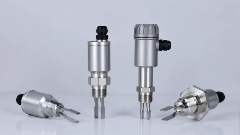
Sor Level Switch 700 Series
Sor Level Switch 700 Series
In the landscape of industrial process control, point level detection remains a critical safety and operational requirement. The SOR Level Switch 700 series represents a foundational technology in this category, utilizing mechanical buoyancy principles to provide reliable switching in high-pressure and high-temperature environments. For engineers and plant operators, understanding the nuances of the 700 series—and how it compares to modern alternatives like those found in the Welk Level Switches portfolio—is essential for ensuring system integrity.
This guide examines the engineering principles, selection criteria, and installation requirements for the SOR 700 series, providing a technical reference for its application in oil and gas, power generation, and chemical processing.
Measurement Principles of Mechanical Level Switches
Before selecting a specific model within the 700 series, it is necessary to understand the physics governing its operation. Mechanical level switches generally fall into two categories: float-operated and displacer-operated. The SOR 700 series primarily utilizes these mechanical movements to actuate an electrical or pneumatic switch.
Float-Operated Mechanisms
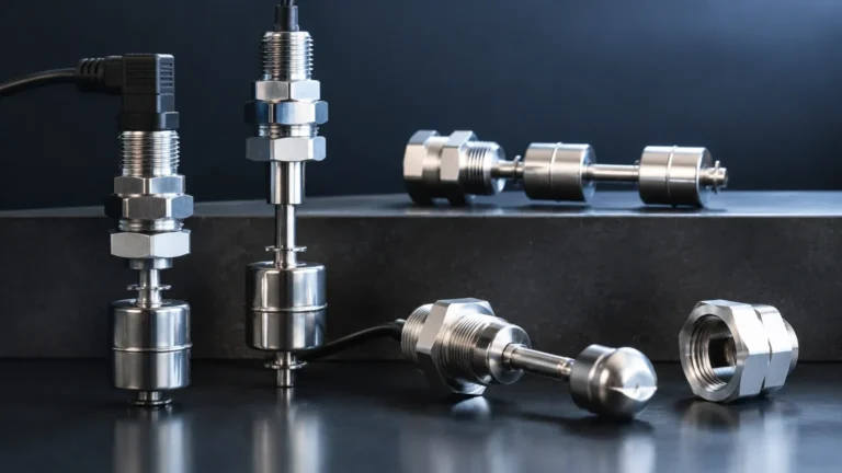
Float-operated switches rely on a buoyant float that is lighter than the process liquid. As the liquid level rises, the float moves upward. In the 700 series, this movement is typically transmitted through a non-magnetic pressure tube. A magnet attached to the float (or an attraction sleeve) moves into the field of a switch mechanism located outside the pressure boundary. This magnetic coupling ensures that the process fluid remains hermetically sealed from the electrical components, preventing leaks and enhancing safety in hazardous areas.
Displacer-Operated Mechanisms
Unlike floats, displacers are heavier than the liquid they are intended to measure. They operate on Archimedes' principle: the buoyant force acting on a body immersed in a fluid is equal to the weight of the fluid displaced by the body. As the liquid level rises and covers more of the displacer, the effective weight of the displacer decreases. This change in weight is detected by a spring mechanism, which then actuates the switch. Displacers are often preferred for applications involving turbulent surfaces or where a wide switching differential is required.
Key Features of the SOR Level Switch 700 Series
The 700 series is engineered for "heavy-duty" service. Its design focuses on modularity and durability, allowing for customization based on specific process conditions. Key technical attributes include:
* Pressure Containment: Designed to handle high-pressure vessels, often rated up to 345 bar (5000 psi) depending on the specific chamber and flange configuration.
* Temperature Resilience: Capable of operating in process temperatures ranging from -54°C to 400°C (-65°F to 750°F).
* Material Versatility: Standard components are often 316 stainless steel, but exotic alloys like Hastelloy or Monel are available for corrosive chemical services.
* Switch Varieties: Options include dry contact micro-switches, hermetically sealed switches for corrosive atmospheres, and pneumatic switch outputs for use in plants without electrical infrastructure.
Technical Selection Criteria
Selecting the correct configuration of a sor level switch 700 series requires a detailed analysis of the process media and the vessel geometry. Engineers must confirm the following parameters before procurement:
1. Specific Gravity (SG)
The buoyancy of a float or the weight change of a displacer is directly tied to the liquid's density. Most 700 series switches are calibrated for a specific SG (e.g., 0.5 for hydrocarbons or 1.0 for water). If the SG varies significantly, the switch point will shift, potentially leading to overflows or dry-run conditions.
2. Operating Pressure and Temperature
The housing (chamber) and the internal float must withstand the maximum possible surge pressure of the system. High-temperature applications may require "cooling fins" or extended brackets to protect the switch housing from heat conduction.
3. Mounting Configuration
The 700 series offers several mounting styles:
* Side-Mounted: The switch chamber is piped to the side of the vessel (external cage).
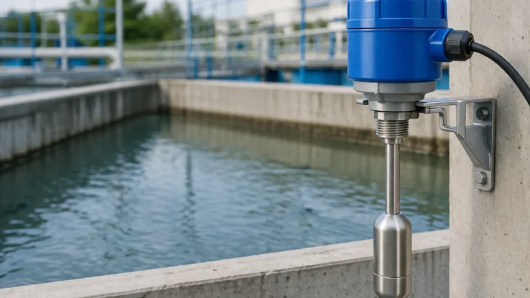
* Top-Mounted: The switch is mounted on a top flange, with the float or displacer suspended into the tank.
Selection Table: SOR 700 Series vs. Application Requirements
| Feature | Float-Operated (701/702) | Displacer-Operated (740/750) | Application Note |
| :— | :— | :— | :— |
| Switching Point | Fixed/Narrow | Adjustable/Wide | Displacers allow for longer spans. |
| Turbulence Resistance | Moderate | High | Displacers are less affected by surface waves. |
| Specific Gravity Min. | 0.40 SG | 0.45 SG | Floats can typically handle lower SG. |
| Max Pressure | Up to 138 bar (2000 psi) | Up to 345 bar (5000 psi) | Displacers are better for ultra-high pressure. |
| Maintenance Access | Requires chamber isolation | Top-access available | Top-mount displacers are easier to pull for inspection. |
Installation and Engineering Considerations
Proper installation is paramount for the longevity of Level Switches. For the SOR 700 series, the following engineering practices should be observed:
Chamber Leveling
External cage switches must be mounted perfectly vertical. Even a few degrees of tilt can cause the float rod to rub against the side of the pressure tube, leading to mechanical friction, delayed response, or total failure to switch.
Piping and Venting
When using external chambers, the piping connecting the chamber to the vessel should be at least 1 inch (25 mm) in diameter to prevent clogging and ensure the level in the chamber accurately tracks the level in the vessel. Equalizing lines (vent and drain) should be installed to facilitate maintenance and calibration checks.
Electrical Wiring
In hazardous environments, the use of explosion-proof conduits is mandatory. Ensure that the conduit seal is poured correctly to prevent the migration of flammable gases into the switch housing. For low-current applications (e.g., connecting to a PLC), gold-plated contacts are recommended to prevent contact oxidation.

Limitations and Potential Risks
While the sor level switch 700 series is robust, it is not a universal solution. Engineers should be aware of the following limitations:
1. Mechanical Wear: As a mechanical device, the pivot points, springs, and seals are subject to wear over time. Regular proof-testing is required in Safety Instrumented Systems (SIS).
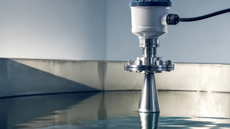
2. Coating and Build-up: If the process fluid is prone to crystallization or heavy scaling, the float or displacer may become stuck. In such cases, non-contact technologies like radar or ultrasonic sensors may be more appropriate.
3. Vibration: High-frequency vibration in the piping or vessel can cause "contact chatter" in mechanical switches, leading to false alarms or premature failure of the electrical contacts.
4. Interface Measurement: While displacers can be used for liquid-liquid interface (e.g., oil and water), the difference in specific gravity must be sufficient (typically >0.1) for reliable operation.
Maintenance and Troubleshooting
To maintain the reliability of a sor level switch 700 series, a preventative maintenance schedule should include:
* Visual Inspection: Check for leaks around flanges and conduit entries.
* Mechanical Function Test: Manually lift the float or displacer (if the chamber design allows) to verify the switch trips and resets correctly.
* Contact Resistance Check: Use a multimeter to ensure the switch contacts are providing a clean, low-resistance path when closed.
* Chamber Flushing: Periodically drain the external cage to remove sediment or sludge that could impede float movement.
Frequently Asked Questions (FAQs)
Q: Can the SOR 700 series be used for steam drum level control?
A: Yes, specific models are designed for high-pressure steam service, but they must be selected with high-temperature gaskets and appropriate pressure ratings (e.g., ASME Class 600 or higher).
Q: What is the difference between a "narrow" and "wide" differential?
A: A narrow differential switch trips and resets within a small change in liquid level (e.g., 15 mm). A wide differential switch (often a displacer type) allows the level to rise significantly before tripping and fall significantly before resetting, which is useful for pump control (on/off cycles).
Q: Are these switches suitable for SIL 2 applications?
A: Many configurations of the 700 series are suitable for use in SIL 2 environments when accompanied by the appropriate FMEDA (Failure Modes, Effects, and Diagnostic Analysis) reports and following strict proof-testing intervals.
Conclusion
The SOR Level Switch 700 series remains a staple in industrial level measurement due to its mechanical simplicity and ability to withstand extreme process conditions. However, the move toward digital transformation and increased safety requirements means that selection must be precise. Whether choosing a traditional mechanical switch or exploring modern Level Switches with advanced diagnostics, engineers must prioritize the chemical compatibility, pressure ratings, and maintenance accessibility of the device.
For complex applications involving viscous fluids or where continuous monitoring is required alongside point level switching, it is recommended to consult with a technical specialist to evaluate if a hybrid approach—combining mechanical switches with electronic transmitters—is the most cost-effective and reliable solution for the long term.