Level Sensor 4 20
Level Sensor 4 20
In the landscape of industrial automation and process control, the transmission of data from the field to the control room requires a reliable, standardized medium. The 4-20mA current loop has remained the global standard for analog signaling for decades. A level sensor 4 20—referring to a continuous level transmitter that outputs a 4 to 20 milliampere signal—provides a linear representation of a tank or vessel's contents, where 4mA typically represents the empty state (0%) and 20mA represents the full state (100%).
This guide examines the engineering principles behind these sensors, the various technologies utilized to generate this signal, and how they integrate with safety systems such as Level Switches to ensure comprehensive monitoring and overfill protection.
Measurement Principles for 4-20mA Transmission
To produce a continuous 4-20mA output, a sensor must first accurately measure the distance to the material surface or the pressure exerted by a liquid column. Different physical principles are applied depending on the medium and environmental conditions.
Radar Level Measurement (ToF)
Radar level transmitters utilize Time of Flight (ToF) technology. The sensor emits high-frequency microwave pulses (often in the 26GHz or 80GHz range). These pulses reflect off the surface of the medium and return to the antenna. The internal electronics calculate the distance based on the travel time and the speed of light, converting this value into a proportional 4-20mA signal. Radar is highly effective for non-contact measurement in high-temperature or high-pressure environments.
Ultrasonic Level Measurement
Similar to radar, ultrasonic sensors use ToF but rely on sound waves. The transducer emits an ultrasonic pulse that travels through the air, hits the surface, and reflects back. Because the speed of sound is affected by air temperature, these sensors usually include a temperature compensation element. The resulting distance is scaled to the 4-20mA output range.
Hydrostatic Pressure Measurement
Hydrostatic level sensors measure the weight of the liquid column above the sensor diaphragm. Based on the formula $P = \rho \cdot g \cdot h$ (where P is pressure, $\rho$ is density, g is gravity, and h is height), the sensor determines the liquid level. A pressure transducer converts the mechanical force into an electrical signal, which is then conditioned into a 4-20mA loop. This is a common choice for water treatment and deep-well applications.
Magnetic Level Transmitters
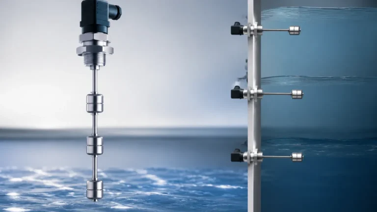
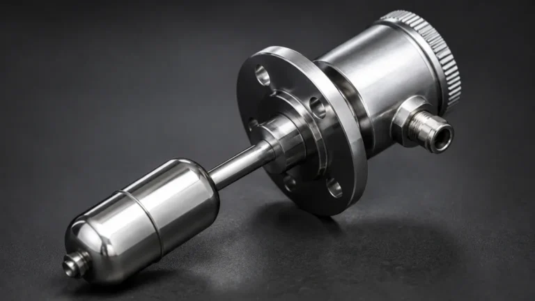
In applications using a magnetic level gauge, a reed chain or magnetostrictive probe can be mounted to the chamber. As a float moves with the liquid level, it triggers a change in resistance or a pulse return time, which the transmitter head converts into a 4-20mA signal. This provides a digital-ready output for a traditionally mechanical visual indicator.
Why Use a 4-20mA Signal?
The preference for a level sensor 4 20 in industrial environments is driven by several technical advantages:
1. Noise Immunity: Unlike voltage signals (e.g., 0-10V), current loops are highly resistant to electromagnetic interference (EMI) and voltage drops over long cable runs. This is critical in plants with heavy machinery and long distances between the vessel and the PLC.
2. Live Zero (4mA): By using 4mA as the baseline for "empty," the system can distinguish between a zero-level reading and a wire break. If the signal drops to 0mA, the control system immediately recognizes a fault.
3. Simplicity of Wiring: Many 4-20mA sensors are "2-wire" devices, meaning the same pair of wires provides power to the sensor and carries the signal, significantly reducing installation costs.
Technical Selection Criteria
Choosing the correct level sensor 4 20 requires an analysis of the process media and the physical constraints of the vessel. The following table provides a comparison of common technologies used to generate a 4-20mA output.
| Technology | Best Suited For | Key Limitation | Typical Accuracy |
| :— | :— | :— | :— |
| Radar | Corrosive liquids, high pressure, foam | High initial cost | ±2 mm to ±5 mm |
| Ultrasonic | Water, wastewater, open channels | Affected by vapor/dust | ±0.25% of range |
| Hydrostatic | Deep tanks, vented vessels | Dependent on fluid density | ±0.1% to ±0.5% |
| Magnetostrictive | Clean liquids, interface levels | Contact-based (requires float) | ±1 mm |
Integration with Level Switches for Safety
While a continuous level sensor 4 20 provides real-time data for process control, it is rarely used in isolation for critical safety functions. Engineering best practices, such as those outlined in SIL (Safety Integrity Level) standards, often require a redundant, independent method for high-level or low-level alarms.
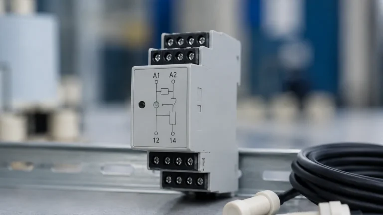
Level Switches serve as this secondary layer of protection. While the 4-20mA transmitter monitors the entire range (e.g., 0 to 10 meters), a point level switch is installed at a specific height to provide a hard-wired contact closure if the level exceeds a safe limit. This ensures that even if the 4-20mA loop fails or the PLC encounters a software error, the hardware switch can directly trigger a pump shutdown or close an inlet valve.

Installation and Wiring Considerations
Proper installation is paramount to maintaining the accuracy of a 4-20mA loop. Engineers should adhere to the following guidelines:
Loop Power Supply
Most 2-wire transmitters require a DC power supply, typically 24V DC. The total resistance in the loop (including the receiver's internal resistance and the wire resistance) must not exceed the transmitter's maximum load capacity, often specified as a "load impedance" curve in the manufacturer's datasheet.
Shielding and Grounding
To prevent signal fluctuations, shielded twisted-pair cables should be used. The shield should be grounded at one end only (usually at the control cabinet) to prevent ground loops, which can introduce significant errors into the 4-20mA signal.
Calibration and Scaling
Calibration involves mapping the physical level to the current output. For instance, in a 5-meter tank:
* 4mA: 0 meters (Bottom of the tank/sensor zero point).
* 12mA: 2.5 meters (50% volume).
* 20mA: 5 meters (Full scale).
Modern digital transmitters often support HART (Highway Addressable Remote Transducer) protocol, which allows for digital configuration and diagnostics to be superimposed on the 4-20mA analog signal.
Limitations and Common Risks
Despite its robustness, the 4-20mA level sensor is subject to certain limitations:
* Signal Attenuation: While current signals travel well, extremely long distances (over 1,000 meters) may require higher voltage power supplies to overcome the cumulative resistance of the wire.
* Medium Density Changes: For hydrostatic sensors, if the density of the liquid changes (e.g., due to temperature fluctuations or mixing different chemicals), the 4-20mA output will become inaccurate unless the system is recalibrated or compensated.
* Environmental Obstructions: For non-contact sensors like ultrasonic or radar, internal tank structures like ladders, agitators, or spray balls can cause false reflections, leading to an incorrect 4-20mA output. Advanced sensors offer "false echo suppression" to ignore these fixed objects.
Frequently Asked Questions (FAQ)
Q: Can I use a level sensor 4 20 for solids?
A: Yes, but technology selection is critical. Radar (specifically high-frequency 80GHz) is generally preferred for solids like powders or grains, as it can penetrate dust better than ultrasonic sensors.
Q: What is the difference between a 2-wire and a 4-wire transmitter?
A: A 2-wire transmitter uses the same two wires for power and signal. A 4-wire transmitter uses two wires for power (often 110V/220V AC or 24V DC) and two separate wires for the 4-20mA signal. 4-wire units are typically used when the sensor requires more power than the 4mA baseline can provide, such as heated sensors or high-power radar units.
Q: How do I troubleshoot a 4-20mA loop that is stuck at 4mA?
A: First, verify the actual level in the tank. If the tank is not empty, check the sensor's configuration for an offset or "zero" error. Use a multimeter in series to measure the actual current. If it is exactly 4.00mA, the sensor may be functioning but incorrectly scaled. If it is 0mA, there is a break in the loop or a loss of power.
Q: Is a 4-20mA signal compatible with modern IoT systems?
A: Yes. Many industrial gateways can convert 4-20mA analog signals into digital protocols like Modbus TCP, MQTT, or OPC UA, allowing the data to be used in cloud-based monitoring and predictive maintenance platforms.
Summary
The level sensor 4 20 remains a cornerstone of industrial process monitoring due to its reliability and standardized nature. By understanding the underlying measurement principles—whether radar, ultrasonic, or hydrostatic—and implementing proper installation techniques, operators can ensure accurate and continuous data flow. However, for high-risk applications, the integration of independent Level Switches remains an essential engineering requirement to provide fail-safe protection against overfills and dry-run conditions.