Level Sensor 4 20ma
Level Sensor 4 20ma
In the landscape of industrial automation, the level sensor 4 20ma remains the most prevalent standard for continuous level measurement. This analog signaling protocol, often referred to as a current loop, provides a robust and reliable method for transmitting data from a field instrument to a control system, such as a PLC (Programmable Logic Controller) or DCS (Distributed Control System). Unlike discrete point-level detection, a 4-20mA sensor provides a real-time, proportional representation of the liquid or solid level within a vessel.
While continuous measurement is essential for process control and inventory management, it is frequently used in conjunction with Level Switches to provide redundant high-level alarms or dry-run protection for pumps. Understanding the principles, selection criteria, and installation requirements of 4-20mA sensors is critical for engineers and plant managers seeking to optimize their industrial processes.
Understanding the 4-20mA Level Measurement Principle
The 4-20mA standard operates on a simple linear relationship. In a typical level measurement application, 4mA represents the "zero" or empty state of the tank (0%), while 20mA represents the "span" or full state (100%). Any value between these two points correlates linearly to the level. For example, a signal of 12mA represents a 50% fill level.
Why 4-20mA is the Industrial Standard
There are several technical reasons why this specific range is preferred over voltage-based signals (like 0-10V):
1. Noise Immunity: Current signals are significantly less susceptible to electromagnetic interference (EMI) and voltage drops over long cable runs, which are common in large industrial facilities.
2. Live Zero: The use of 4mA as the baseline (rather than 0mA) allows the control system to distinguish between a zero-level reading and a broken wire. If the signal drops to 0mA, the system immediately recognizes a loop failure.
3. Power Delivery: In many "two-wire" configurations, the same two wires that carry the 4-20mA signal also provide the power required to operate the sensor, simplifying wiring and reducing costs.
Core Technologies Utilizing 4-20mA Outputs
Several measurement principles can be used to generate this output signal, depending on the application requirements:
* Hydrostatic Pressure: These sensors measure the weight of the liquid column above the sensor diaphragm. The pressure ($P$) is proportional to the height ($h$) of the liquid and its density ($
ho$), following the formula $P =
ho gh$. The sensor converts this pressure into a 4-20mA signal.
* Ultrasonic: These are non-contact sensors that emit high-frequency sound pulses. By measuring the time-of-flight (the time it takes for the pulse to hit the surface and return), the sensor calculates the distance and converts it to a level percentage.
* Radar (GWR and Non-Contact): Similar to ultrasonic but using microwave pulses. Radar is unaffected by air temperature, vacuum, or high pressure, making it ideal for volatile or high-temperature environments.
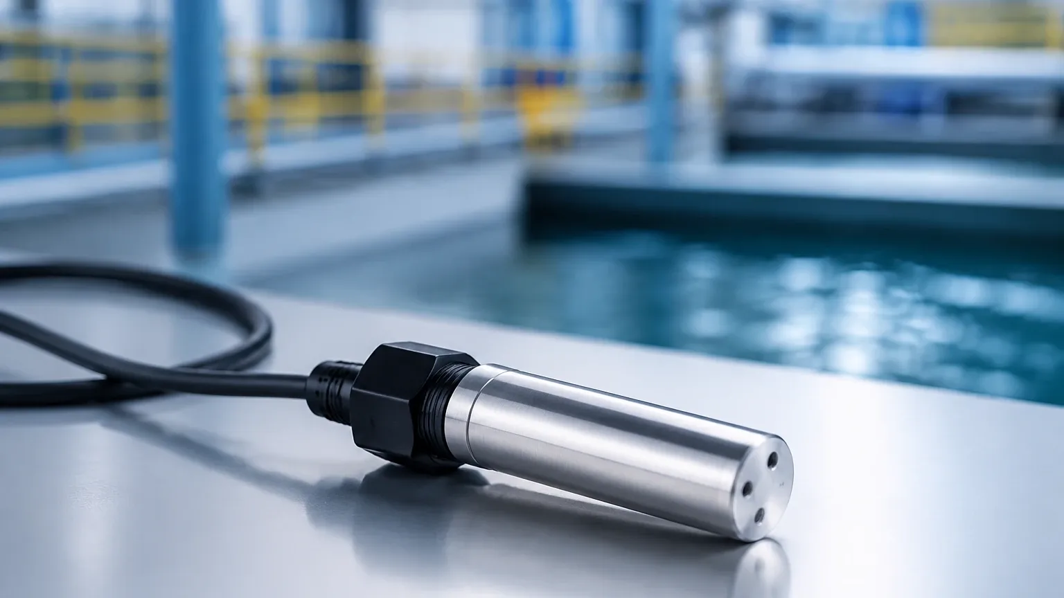
* Submersible Transmitters: A variation of hydrostatic sensors designed to be lowered into deep wells or open water bodies, providing a 4-20mA signal based on the depth of immersion.
Comparing Technologies for 4-20mA Level Sensors
Selecting the right technology depends heavily on the media being measured and the environmental conditions. The following table provides a comparison of common 4-20mA level measurement technologies.
| Technology | Contact Type | Ideal Applications | Limitations | Typical Accuracy |
| :— | :— | :— | :— | :— |
| Hydrostatic | Contact | Water tanks, fuel storage, deep wells | Affected by changes in liquid density | ±0.25% to ±0.5% |
| Ultrasonic | Non-contact | Water treatment, chemical storage | Sensitive to foam, vapor, and heavy dust | ±0.25% of range |
| Radar (80GHz) | Non-contact | Corrosive chemicals, high-temp solids | Higher initial cost | ±1 mm to ±3 mm |
| Guided Wave Radar | Contact | Small tanks, liquids with low dielectric | Subject to material build-up on the probe | ±2 mm |
| Magnetic Level Gauge | Contact | Boiler drums, high-pressure vessels | Requires a bypass chamber or external cage | ±5 mm |
Integrating Level Switches for Redundant Safety
In a professional engineering setup, a level sensor 4 20ma is rarely the only instrument on a tank. While the 4-20mA signal is used for active control—such as modulating a valve or adjusting pump speed—it is considered best practice to install independent Level Switches for safety-critical functions.
Continuous sensors can fail due to power loss, signal interference, or scaling on the sensing element. A mechanical or vibratory level switch acts as a hard-wired fail-safe. If the level reaches a dangerous high point, the switch can directly trip a relay to shut down the fill pump, regardless of what the 4-20mA sensor is reporting. This layered approach is often a requirement for compliance with functional safety standards like SIL (Safety Integrity Level).
Selection Criteria and Application Engineering
Before specifying a level sensor 4 20ma, several technical parameters must be confirmed to ensure long-term reliability.
1. Media Characteristics
* Density: For hydrostatic sensors, any change in the specific gravity of the liquid will result in an error. If the density varies, a radar or ultrasonic sensor is a better choice.
* Corrosiveness: Ensure the wetted parts (316L stainless steel, PTFE, PP, or PVDF) are compatible with the chemical composition of the media.
* Viscosity and Coating: If the media is sticky (like molasses or heavy oil), contact-based sensors may fail due to build-up. Non-contact radar is preferred here.
2. Process Conditions
* Temperature: Standard ultrasonic sensors are usually limited to 60°C or 80°C. For steam or high-temperature processes (up to 250°C or higher), specialized radar sensors are required.
* Pressure: Hydrostatic and radar sensors can handle high-pressure environments, whereas ultrasonic sensors cannot operate in a vacuum because sound requires a medium to travel through.
3. Vessel Geometry
* Dead Zones: Every sensor has a "dead zone" (blocking distance) at the very top of its range where it cannot measure. For a sensor with a 0.3m dead zone, the tank can never be filled closer than 0.3m to the sensor face without losing the signal.
* Obstructions: Internal structures like agitators, ladders, or heating coils can create false echoes for ultrasonic and radar sensors. Modern sensors offer "false echo suppression" software to ignore these fixed objects.
Installation and Wiring Guidelines for 4-20mA Loops
Proper installation is the most critical factor in preventing signal instability.
Wiring Configurations
* 2-Wire (Loop Powered): The sensor is wired in series with the power supply and the load (PLC input). This is the most common configuration for industrial sensors. The power supply is typically 24V DC.
* 3-Wire or 4-Wire: These are used when the sensor requires more power than the 4mA baseline can provide (e.g., for heated displays or high-power radar). The power supply and the signal loop are separate.
Mounting Considerations
* Positioning: Sensors should be mounted away from the fill inlet to avoid turbulence and air entrainment. For hydrostatic sensors, ensure they are not placed in areas of high flow where the "Bernoulli effect" might cause false pressure readings.
* Stilling Wells: In tanks with heavy agitation or foam, installing the sensor inside a stilling well (a vertical pipe) can provide a calm surface for more accurate measurement.
* Cable Shielding: Always use shielded twisted-pair cabling. The shield should be grounded at only one end (usually the control cabinet) to prevent ground loops.
Troubleshooting and Common Operational Risks
Even the highest quality level sensor 4 20ma can encounter issues in the field. Common risks include:
1. Signal Clipping: If the level exceeds the calibrated span, the sensor may output more than 20mA (e.g., 21mA or 22mA). Most PLCs can be programmed to recognize this as an "over-range" error.
2. Moisture Ingress: In humid environments, condensation can enter the sensor housing if the cable glands are not properly tightened or if the vent tube (in hydrostatic sensors) is blocked. Using a desiccant filter on the vent tube is a common preventive measure.
3. Loop Resistance: Every component in the loop (wires, barriers, indicators, PLC inputs) adds resistance. If the total resistance is too high, the 24V DC power supply may not be able to drive the full 20mA signal. Always calculate the total loop impedance against the sensor’s maximum load capacity.
Frequently Asked Questions
Q: Can a 4-20mA sensor be used for solids?
A: Yes, but technology choice is vital. Non-contact radar or ultrasonic sensors are commonly used for grain, powders, and plastic pellets. However, dust and the "angle of repose" of the solid material must be accounted for during calibration.
Q: How often should a 4-20mA level sensor be calibrated?
A: Most modern digital sensors are very stable. An annual calibration check is standard for most industrial applications, though high-precision or regulated industries (like pharma or food) may require more frequent validation.
Q: What is the maximum distance for a 4-20mA signal?
A: Depending on the wire gauge and the power supply voltage, a 4-20mA signal can typically travel up to 1,000 meters without significant degradation, provided proper shielding is used to mitigate noise.
Q: What happens if the power supply fluctuates?
A: Most industrial-grade sensors have internal voltage regulators. As long as the supply stays within the sensor’s specified range (e.g., 12-36V DC), the 4-20mA output will remain accurate.
By carefully matching the sensor technology to the process media and ensuring a robust electrical installation, a level sensor 4 20ma provides the high-resolution data necessary for efficient industrial automation. When paired with independent Level Switches for critical alarms, these instruments form the foundation of a safe and productive fluid management system.