Level Sensor in Tank
Level Sensor in Tank
In industrial process control, selecting the appropriate level sensor in tank applications is a critical engineering decision that affects safety, efficiency, and inventory management. Whether managing bulk storage of chemicals, treating wastewater, or monitoring fuel reserves, the choice of technology depends on the physical properties of the media, the geometry of the vessel, and the specific requirements of the control system. This guide provides a technical overview of level measurement principles, selection criteria, and installation best practices for professional engineers and plant operators.
Understanding Level Measurement Principles
Before selecting a level sensor in tank environments, it is essential to distinguish between the two primary modes of measurement: continuous level measurement and point level detection. Continuous measurement provides a real-time tracking of the fluid level across the entire height of the tank, while point level detection—often facilitated by Level Switches—triggers an alert or action when the media reaches a specific threshold, such as high-level overfill or low-level dry-run protection.
Radar Level Measurement (Non-Contact)
Radar level meters utilize Time-of-Flight (ToF) technology. High-frequency microwave pulses (typically at 26GHz or 80GHz) are emitted from the sensor antenna, reflected off the surface of the media, and received by the sensor. The distance is calculated based on the time interval between emission and reception.
* Advantages: Immune to changes in temperature, pressure, and dust. Highly accurate (up to ±1mm).
* Limitations: Requires a minimum dielectric constant ($ε_r$) of the media to reflect the signal effectively.
Ultrasonic Level Measurement
Ultrasonic sensors emit high-frequency sound waves that bounce off the liquid surface. Like radar, they use the ToF principle. These are widely used in water treatment and open-tank applications.
* Advantages: Cost-effective and non-contact.
* Limitations: Sensitive to surface foam, heavy vapor, and temperature fluctuations, as the speed of sound changes with air density.
Hydrostatic Level Measurement
This principle relies on the relationship between the height of a liquid column and the pressure it exerts at the base of the tank. The formula $P = ρ · g · h$ (where $P$ is pressure, $ρ$ is density, $g$ is gravity, and $h$ is height) allows the sensor to calculate the level based on the weight of the fluid.
* Advantages: Simple to install (submersible or flange-mounted) and very reliable for vented tanks.
* Limitations: Changes in fluid density (due to temperature or composition changes) will lead to measurement errors unless compensated.
Guided Wave Radar (GWR)
GWR uses a probe (cable or rod) to guide the microwave pulse directly to the media surface. This is a contact-based measurement technology.
* Advantages: Excellent for low-dielectric fluids and environments with heavy steam or foam.
* Limitations: The probe is subject to coating or physical damage from agitators.
Practical Selection Table for Tank Level Sensors
The following table summarizes technology recommendations based on common industrial media and tank conditions.
| Media Type | Recommended Technology | Primary Benefit | Potential Limitation |
| :— | :— | :— | :— |
| Water / Wastewater | Ultrasonic or Radar | Non-contact, low maintenance | Foam can absorb ultrasonic signals |
| Corrosive Chemicals | PTFE-coated Radar | Chemical resistance | High cost for exotic materials |
| Viscous Oils | Guided Wave Radar | Reliable in low $ε_r$ | Material buildup on the probe |
| Solids / Powders | High-frequency Radar (80GHz) | Penetrates dust | Steep angle of repose |
| High Pressure/Temp | Hydrostatic or GWR | Robust mechanical seals | Density compensation required |
| Point Detection | Level Switches | Redundancy and safety | Only detects specific points |
Critical Factors for Level Sensor in Tank Selection
When evaluating a level sensor in tank setups, engineers must confirm several parameters to ensure long-term reliability.
1. Media Properties
The chemical compatibility of the sensor wetted parts is paramount. For example, concentrated sulfuric acid requires PTFE or PVDF housings, while food-grade applications require 316L stainless steel with sanitary fittings. Additionally, the dielectric constant of the liquid determines whether a non-contact radar will receive a strong enough echo.
2. Tank Geometry and Obstructions
Internal structures such as heating coils, agitators, and ladders can create "false echoes" for ultrasonic and radar sensors. In narrow tanks or tanks with complex internals, a high-frequency 80GHz radar is often preferred due to its narrow beam angle (as small as 3 degrees), which allows it to bypass obstructions. Alternatively, a bypass chamber (side-mounted) can be used to isolate the measurement from the main tank turbulence.
3. Process Conditions
Temperature and pressure ranges must be within the sensor's operating envelope. Standard ultrasonic sensors are typically limited to 80°C (176°F), whereas specialized radar sensors can handle process temperatures exceeding 450°C (842°F). For pressurized vessels, hydrostatic transmitters must be used in a differential pressure (DP) configuration to subtract the headspace pressure from the total bottom pressure.
Installation Considerations and Best Practices
Correct installation is as important as selecting the right technology. Poor placement of a level sensor in tank environments is the leading cause of signal loss and inaccurate readings.
* Nozzle Geometry: For radar and ultrasonic sensors, the nozzle height should be kept as short as possible. If the nozzle is too long or narrow, the signal may reflect off the nozzle walls before reaching the tank interior.
* The 1/6th Rule: For cylindrical tanks with flat tops, a common rule of thumb is to install the sensor at 1/6th of the tank diameter away from the side wall. This avoids the center of the tank (where multiple reflections can occur) and the wall (where interference is high).
* Avoiding the Inflow: Never install a level sensor directly above the fill pipe. The turbulence and air entrainment from the incoming fluid will cause erratic readings.
* Dead Zones: Every sensor has a "blocking distance" or dead zone near the antenna where measurement is impossible. Ensure the sensor is mounted high enough that the maximum liquid level never enters this zone.
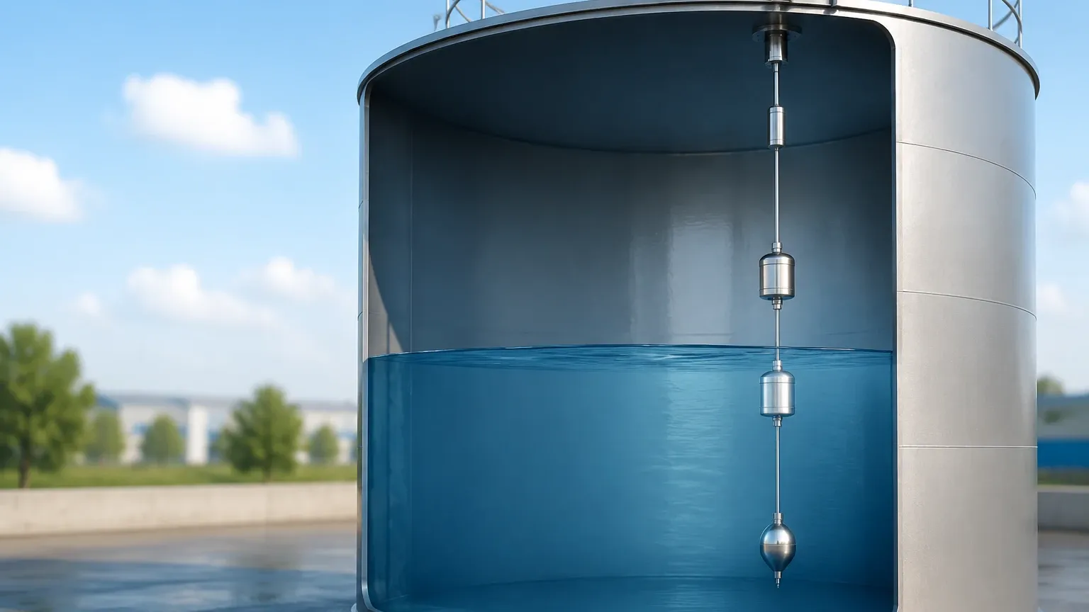
The Role of Level Switches in Tank Safety
While continuous sensors provide the data needed for process control, Level Switches serve as the primary line of defense for safety-critical functions. In many jurisdictions, industrial tanks are required by law to have an independent high-level alarm system that is separate from the continuous level transmitter.
Common types of switches used in tanks include:
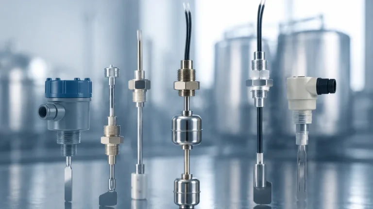
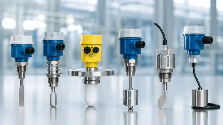
* Vibrating Tuning Forks: Ideal for liquids; they detect the change in frequency when the fork is submerged.
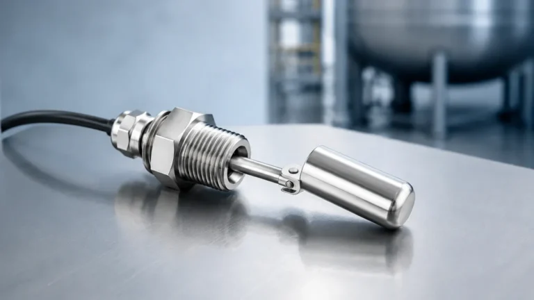
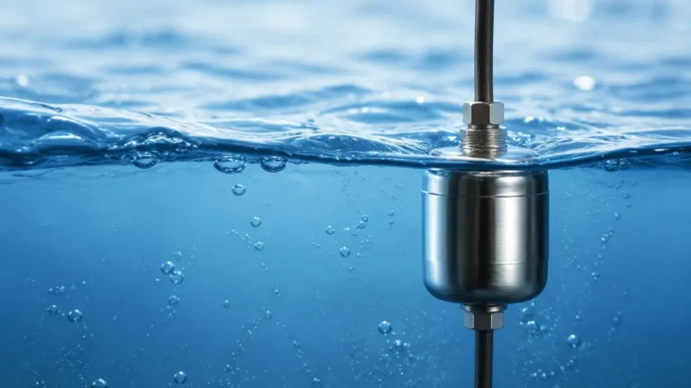
* Float Switches: A simple, mechanical solution where a magnetic float moves with the liquid level to trigger a reed switch.
* Capacitance Switches: Detect the change in electrical capacitance when the media touches the probe, suitable for both liquids and solids.
Using a combination of a continuous level sensor in tank applications alongside a high-level switch provides the redundancy necessary for SIL (Safety Integrity Level) rated systems.
Limitations and Environmental Challenges
No single technology is a universal solution. Engineers should be aware of the following limitations:
1. Foam: Heavy, dense foam can absorb ultrasonic and radar signals. In these cases, Guided Wave Radar or Hydrostatic sensors are more reliable.
2. Vapor and Condensation: In closed tanks, condensation can form on the sensor face. Some radar sensors feature a "drip-off" antenna design to prevent water droplets from interfering with the signal.
3. Vacuum Conditions: Ultrasonic sensors cannot function in a vacuum because sound waves require a medium (air/gas) to travel. Radar or hydrostatic sensors must be used instead.
Frequently Asked Questions (FAQ)
Q: Can I use an ultrasonic sensor for a diesel fuel tank?
A: It is generally not recommended for indoor or pressurized fuel tanks due to the presence of vapors which change the speed of sound, leading to errors. A radar sensor or hydrostatic transmitter is a better choice for fuel.
Q: How do I measure the level in a tank with an agitator?
A: Use a radar sensor with a narrow beam angle and enable "false signal suppression" in the software to ignore the agitator blades. Alternatively, use a bypass pipe (stilling well) to provide a calm surface for measurement.
Q: What is the difference between a 2-wire and 4-wire level sensor?
A: A 2-wire sensor uses the same two wires for both power and the 4-20mA output signal, which simplifies wiring. A 4-wire sensor has separate wires for power and signal, which is often necessary for power-intensive features like heated displays or high-power long-range transducers.
Q: How often should a level sensor in tank be calibrated?
A: For non-contact sensors like radar, the electronics are very stable, and annual verification is usually sufficient. Hydrostatic sensors may require more frequent calibration (every 6 months) if the media is prone to coating the diaphragm.
Conclusion
Achieving accurate level measurement requires a holistic view of the application. By understanding the physics of the measurement—whether it be the microwave reflection of a radar or the pressure sensing of a hydrostatic transmitter—and pairing that with robust Level Switches for safety, operators can ensure reliable tank monitoring. Always confirm the chemical compatibility, pressure ratings, and tank internals with the instrument manufacturer before finalizing the installation of any level sensor in tank systems.