Level Switch Buoyancy
Level Switch Buoyancy
In the field of industrial process control, the principle of buoyancy remains one of the most reliable and widely utilized methods for point level detection. Buoyancy-based level switches operate on the fundamental physics of fluid displacement to provide high-level alarms, low-level protection, and pump control across diverse industries. Understanding the mechanics of level switch buoyancy is essential for engineers and plant operators to ensure accurate switching, especially when dealing with varying fluid densities, high pressures, or corrosive environments.
As a professional manufacturer of industrial level measurement instruments, Welk provides a range of Level Switches designed to leverage buoyancy for precise automation in water treatment, chemical processing, and oil and gas applications.
The Physics of Level Switch Buoyancy
The operation of buoyancy-based level switches is governed by Archimedes' Principle. This principle states that any object, wholly or partially immersed in a fluid, is buoyed up by a force equal to the weight of the fluid displaced by the object.
Mathematically, the buoyant force ($F_b$) is expressed as:
$$F_b = \rho \cdot V \cdot g$$
Where:
* $\rho$ (rho): The density of the liquid (kg/m³).
* V: The volume of the displaced liquid (m³).
* g: The acceleration due to gravity (approximately 9.81 m/s²).
In the context of level switches, this force is used to actuate a mechanical or electronic switch. There are two primary ways this principle is applied: the float method and the displacer method.
The Float Principle
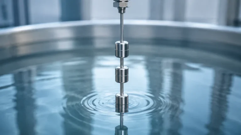
In a float-operated level switch, the sensing element (the float) is designed to be less dense than the process liquid. Because the float is lighter than the liquid it displaces, it remains on the surface. As the liquid level rises or falls, the float moves accordingly. This movement is typically transmitted through a rod or a flexible cable to a switching mechanism, such as a microswitch or a reed switch.
The Displacer Principle
Unlike a float, a displacer is designed to be heavier than the process liquid, meaning it would naturally sink if not suspended. The displacer is hung from a spring or a torque tube. When the liquid rises and covers the displacer, the buoyant force increases, which reduces the apparent weight of the displacer. This change in weight (rather than the movement of the surface itself) is what triggers the switch. Displacers are often preferred in high-pressure applications or where the liquid surface is turbulent.
Key Evaluation Criteria for Buoyancy Switches
To ensure a level switch functions correctly, several physical parameters must be evaluated during the selection process. Failure to account for these can lead to "float failure," where the switch stays submerged or fails to rise.
Specific Gravity (SG)
Specific gravity is the ratio of the density of the process liquid to the density of water at a specified temperature. Most buoyancy switches are rated for a minimum specific gravity. If the liquid's SG is lower than the float's design limit, the float will not displace enough mass to generate the force required to move the switching mechanism. For example, a float designed for water (SG 1.0) may sink in a light hydrocarbon like propane (SG 0.5).
Operating Pressure and Temperature
Temperature affects the density of the liquid; as temperature increases, density typically decreases, which reduces the available buoyant force. Furthermore, high pressure can collapse hollow floats. For high-pressure applications, solid floats or heavy-walled stainless steel floats are required to maintain structural integrity and consistent buoyancy.
Liquid Viscosity
High-viscosity liquids can create "drag" on the float, slowing its response time. In extreme cases, thick or sticky fluids can cause the float to adhere to the tank wall or the guide rod, leading to false readings or mechanical failure.
Practical Selection Table
Choosing the right technology depends on the specific requirements of the tank and the medium. The following table compares common buoyancy-based level switches.
| Switch Type | Operating Principle | Ideal Applications | Typical Min. SG | Advantages |
| :— | :— | :— | :— | :— |
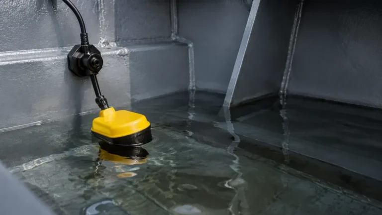
| Side-Mounted Float | Buoyancy (Lever) | High/Low alarm in small tanks | 0.6 – 0.8 | Compact, easy to install horizontally. |
| Vertical Float | Buoyancy (Magnetic) | Multi-point detection in clean liquids | 0.45 – 0.7 | Reliable, supports multiple switch points on one rod. |
| Displacer Switch | Buoyancy Change | High pressure, turbulent sumps | 0.4 – 0.5 | Extremely rugged, handles turbulence well. |
| Cable Float | Buoyancy (Tilt) | Sewage, water pits, open sumps | 0.9 – 1.0 | Low cost, resistant to fouling and debris. |
| Interface Float | Differential Buoyancy | Oil/Water separation tanks | Specific to SG Delta | Detects the boundary between two liquids. |
Installation Considerations
Proper installation is critical to maintaining the mechanical advantage provided by buoyancy. Engineers should consider the following factors:
1. Stilling Wells: In tanks with heavy agitation or splashing, a float can bounce, causing "chatter" in the electrical circuit. Installing the float or displacer inside a stilling well (a vertical pipe with vent holes) protects the sensor from turbulence and ensures a stable buoyancy force.
2. Mounting Orientation: Float switches are typically mounted either vertically from the top or horizontally from the side. Horizontal floats use a lever arm to increase the force applied to the switch, making them effective for liquids with slightly lower specific gravities.
3. Clearance: Ensure there is sufficient clearance between the float and the tank walls, heaters, or internal baffles. Any mechanical obstruction will prevent the float from rising, negating the buoyancy principle.
4. Specific Gravity Calibration: For displacer switches, the spring tension must be calibrated to the specific gravity of the liquid. If the liquid density changes significantly due to process variations, the switch point will drift.

Limitations and Risks
While level switch buoyancy is a proven technology, it is not universal. Certain conditions can compromise its accuracy:
* Material Build-up: In applications like wastewater or lime slurry, material can coat the float. This increases the weight of the float and changes its volume, eventually causing it to sink or stick.
* Vapor Space Density: In very high-pressure gas applications, the density of the vapor above the liquid can become significant. This reduces the *net* buoyant force, as the float is no longer moving from a vacuum/air into a liquid, but from a dense gas into a liquid.
* Mechanical Wear: Because these are mechanical systems, pivot points and springs are subject to wear over millions of cycles. Regular inspection of the moveables is necessary in critical safety loops.
Frequently Asked Questions (FAQs)
1. Can a float switch be used for interface level detection?
Yes. By weighting a float so that its density is between the densities of two immiscible liquids (e.g., heavier than oil but lighter than water), the float will sink through the upper layer and float on the lower layer. This is a common method for detecting the interface in separator tanks.
2. How does temperature affect level switch buoyancy?
As temperature rises, most liquids expand and their density (specific gravity) decreases. Since the buoyant force is directly proportional to density, a float will sit lower in a hot liquid than in a cold one. If the liquid becomes too thin, the float may fail to actuate the switch.
3. What is the difference between a reed switch float and a microswitch float?
Reed switch floats use a magnet inside the float to actuate a hermetically sealed reed switch in the stem. These are ideal for low-power signals and corrosive environments. Microswitch floats usually involve a mechanical linkage or a rolling ball that triggers a snap-action switch, suitable for higher electrical loads.
4. Why would I choose a displacer over a standard float?
Displacers are generally more stable in turbulent conditions because they are heavier and less prone to bobbing on the surface. They are also easier to test; since they are suspended, an operator can manually lift the suspension wire to simulate a high-level condition without filling the tank.
Conclusion
Level switch buoyancy remains a cornerstone of industrial level control due to its simplicity and physical reliability. By understanding the relationship between fluid density, displacement volume, and mechanical force, engineers can select the most appropriate Level Switches for their specific process conditions. Whether utilizing a simple tilt float for a sump pump or a sophisticated magnetic displacer for a high-pressure reactor, respecting the laws of buoyancy ensures long-term operational safety and efficiency.
For complex applications involving aggressive chemicals or extreme temperatures, consulting with a manufacturer like Welk can help in customizing float materials and switch configurations to meet exact site requirements.