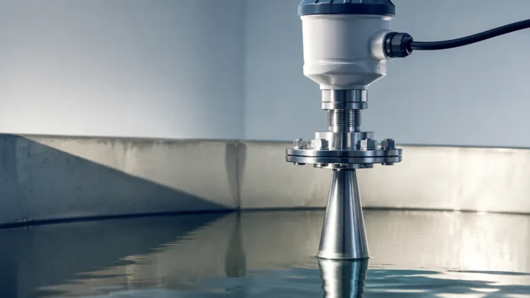
Level Sensor Indicator
Level Sensor Indicator
In the landscape of industrial automation and process control, a level sensor indicator serves as the critical bridge between physical storage states and actionable data. Whether managing a municipal water reservoir, a chemical mixing tank, or a complex oil-water separator, engineers require precise, real-time feedback to maintain operational safety and efficiency. A level sensor indicator is not merely a single device but often a system comprising a primary sensing element, a transmitter, and a visual or digital display interface that interprets the presence or volume of media within a vessel.
Selecting the appropriate technology requires a deep understanding of the physical principles governing different measurement methods. From non-contact radar systems to robust mechanical switches, the choice of indicator impacts everything from maintenance cycles to the accuracy of inventory management.
Measurement Principles of Level Indicators
Before selecting a level sensor indicator, it is essential to understand the physics behind the measurement. Industrial instruments generally fall into two categories: continuous measurement and point level detection.
1. Time-of-Flight (Radar and Ultrasonic)
Radar and ultrasonic sensors operate on the time-of-flight (ToF) principle. The sensor emits a signal—either an electromagnetic pulse in the case of radar or a sound wave for ultrasonic—which travels through the air or gas space, reflects off the surface of the medium, and returns to the transducer.
* Radar: Uses high-frequency microwave pulses (typically 26GHz or 80GHz). Because electromagnetic waves are unaffected by air temperature, pressure, or vacuum, radar is the preferred level sensor indicator for volatile or high-pressure environments.
* Ultrasonic: Relies on sound waves. The speed of sound is affected by air density and temperature, necessitating built-in temperature compensation. These are cost-effective for open-air water applications but are limited in high-dust or high-pressure scenarios.
2. Hydrostatic Pressure
Hydrostatic level indicators measure the pressure exerted by a liquid column at the bottom of a tank. Based on the formula $P = \rho gh$ (where $P$ is pressure, $\rho$ is density, $g$ is gravity, and $h$ is height), the sensor converts the measured pressure into a level reading. This method is highly effective for vented tanks with liquids of constant density. In pressurized tanks, a differential pressure (DP) transmitter is used to subtract the head pressure from the total pressure.
3. Magnetic and Visual Indication
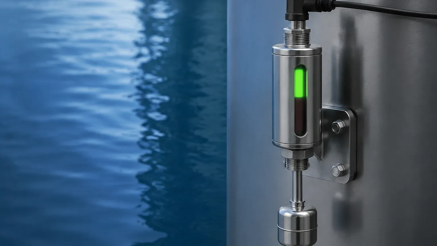
Magnetic level gauges utilize a float containing an internal magnet assembly. As the liquid level changes, the float moves a series of bi-color magnetic flaps or a follower on an external scale. This provides a clear, high-visibility visual level sensor indicator that requires no power to operate, making it ideal for safety-critical local monitoring.
4. Point Level Detection
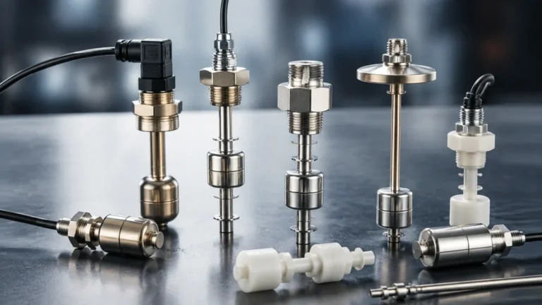
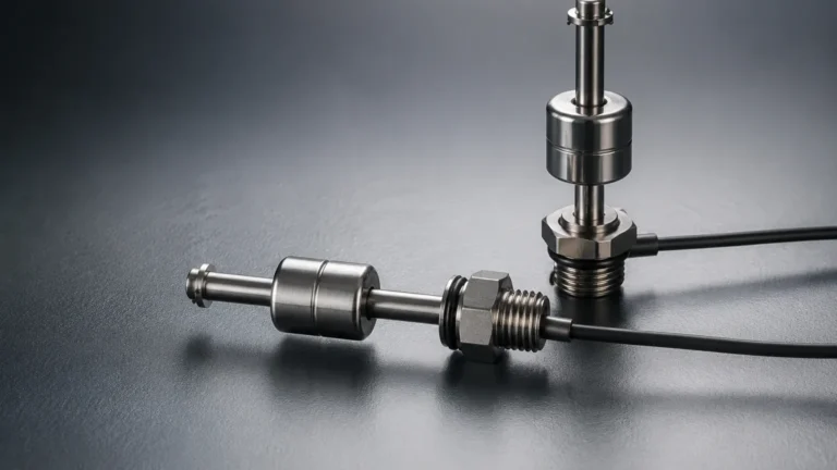
While continuous sensors provide a 0-100% reading, Level Switches provide binary feedback (on/off) at specific heights. These are used for overfill protection, dry-run prevention for pumps, and high/low-level alarms. Technologies include tuning forks (vibration), capacitive probes, and float switches.
The Role of Level Switches in System Redundancy
In a professional process environment, relying solely on a continuous level sensor indicator can be a risk. If a radar sensor experiences a signal loss due to heavy foam or a power failure, the system may lose track of the actual volume. This is where point level detection becomes indispensable.
Integrating Level Switches as secondary indicators provides a fail-safe mechanism. For instance, a tuning fork level switch installed at the 95% mark of a tank can trigger an emergency shutdown (ESD) independently of the primary continuous sensor. This layered approach to level indication is a standard requirement in industries governed by SIL (Safety Integrity Level) ratings, such as petrochemical and pharmaceutical manufacturing.
Practical Selection Criteria
Choosing the right level sensor indicator involves evaluating the media properties and the vessel's physical constraints. The following table provides a comparison of common technologies used in industrial applications.
Technology Comparison Table
| Technology | Media Type | Measuring Range | Max Temperature | Max Pressure | Accuracy |
| :— | :— | :— | :— | :— | :— |
| Radar (80GHz) | Liquids/Solids | Up to 120m (393 ft) | 250°C (482°F) | 40 bar (580 psi) | ±1 mm |
| Ultrasonic | Liquids/Slurries | Up to 30m (98 ft) | 80°C (176°F) | 3 bar (43 psi) | ±0.25% FS |
| Hydrostatic | Clean Liquids | Up to 200m (656 ft) | 100°C (212°F) | N/A (Submersible) | ±0.5% FS |
| Magnetic Gauge | Liquids | Up to 6m (20 ft) | 400°C (752°F) | 160 bar (2320 psi) | Visual |
| Level Switches | Liquid/Solid | Point Specific | 150°C (302°F) | 64 bar (928 psi) | ±1 mm |
Key Considerations for Evaluation:
1. Media Dielectric Constant: Radar sensors require a minimum dielectric constant ($ε_r$) to reflect the signal. For low $ε_r$ fluids like oils, guided wave radar or hydrostatic sensors may be more appropriate.
2. Chemical Compatibility: Ensure the wetted materials (e.g., SS316L, PTFE, PP, or Hastelloy) are resistant to the process media.
3. Output Requirements: Modern indicators typically offer 4-20mA HART, RS485 Modbus, or Profibus. For remote monitoring, wireless LoRaWAN or NB-IoT options are increasingly common.
Installation Considerations and Best Practices
Correct installation is as vital as selecting the right technology. A high-quality level sensor indicator will perform poorly if mounted incorrectly.
* Avoid Obstructions: For non-contact sensors (Radar/Ultrasonic), the signal beam must be kept away from internal tank structures like ladders, agitators, or heating coils. If obstructions are unavoidable, look for sensors with "false signal suppression" software.
* Nozzle Geometry: The height and diameter of the mounting nozzle can interfere with the sensor's "dead zone" (blocking distance). Ensure the sensor face extends slightly beyond the nozzle or that the nozzle height is within the manufacturer's specifications.
* Mounting Location: Sensors should generally not be mounted in the center of a tank (to avoid multiple reflections) or too close to the wall (to avoid signal attenuation). A common rule of thumb is to mount the sensor at 1/4 to 1/3 of the tank diameter from the wall.
* Stilling Wells: In tanks with heavy turbulence or foam, installing the level sensor indicator inside a stilling well or bypass chamber can provide a stable surface for measurement.
Limitations and Potential Risks
While modern instrumentation is robust, certain environmental factors can compromise accuracy:
* Foam and Turbulence: Heavy foam can absorb ultrasonic and radar signals, leading to a "lost echo" error. In these cases, hydrostatic transmitters or magnetic level gauges are more reliable.
* Build-up and Coating: In sticky media like molasses or wastewater sludge, material can build up on the sensor face. While many radar sensors can "see through" thin coatings, significant build-up will eventually cause measurement drift.
* Vapor and Dust: Dense steam or heavy dust (in grain silos) can attenuate ultrasonic signals. High-frequency radar is typically the solution for these environments.
* Ambient Temperature: For outdoor installations, indicators with LCD screens must be rated for the local climate. Extreme cold can cause displays to freeze, while extreme heat can damage internal electronics without proper sunshades.
Frequently Asked Questions (FAQ)
Q: Can a level sensor indicator be used for both liquids and solids?
A: Some technologies, like radar and certain level switches, are versatile enough for both. However, ultrasonic sensors often struggle with solids due to the uneven reflection surface and dust. Always verify the sensor is calibrated for the specific material density and angle of repose.
Q: What is the difference between a level transmitter and a level indicator?
A: A transmitter is the component that measures the level and converts it into an electrical signal (like 4-20mA). An indicator is the component that displays that value. Many modern industrial devices combine both into a single unit.
Q: How often should a level sensor indicator be calibrated?
A: This depends on the industry and the technology. Hydrostatic sensors may require annual calibration due to sensor drift. Radar and ultrasonic sensors are generally more stable but should be verified during scheduled plant turnarounds or if process conditions change significantly.
Q: Is it possible to monitor tank levels remotely?
A: Yes. Most level sensor indicators can be integrated into a PLC, SCADA system, or cloud-based monitoring platform via digital protocols like Modbus or through cellular gateways. This allows for inventory management across multiple sites from a central office.
Q: What happens if the power fails?
A: Most electronic indicators will hold their last value or drop to a failure state (e.g., 3.6mA or 21mA). For critical safety, mechanical indicators like magnetic level gauges are recommended because they continue to provide a visual reading without electrical power.
By carefully matching the measurement principle to the application and ensuring redundant safety through Level Switches, facility managers can ensure accurate, reliable, and safe level monitoring for any industrial process.