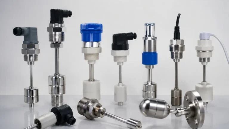
Level Sensor in Water Tank
Level Sensor in Water Tank
Accurate level measurement in water tanks is a fundamental requirement across various sectors, including municipal water treatment, industrial process cooling, fire protection systems, and agricultural irrigation. Selecting the appropriate level sensor in a water tank involves understanding the physical properties of the liquid, the container's geometry, and the specific operational requirements of the system. This guide provides a detailed engineering perspective on the technologies available, their measurement principles, and practical selection criteria for industrial applications.
Understanding Measurement Principles for Water Tank Level Sensing
Industrial level measurement is broadly categorized into continuous level monitoring and point level detection. Choosing between these depends on whether the application requires real-time volume tracking or simply automated control of pumps and valves.
Ultrasonic Level Measurement
Ultrasonic sensors operate on the "Time-of-Flight" principle. The sensor, mounted at the top of the tank, emits high-frequency sound waves that travel through the air, reflect off the water surface, and return to the transducer. The distance is calculated based on the time interval between emission and reception.
* Advantages: Non-contact measurement prevents contamination and corrosion. It is highly effective for standard water storage where the surface is relatively calm.
* Limitations: Ultrasonic waves can be affected by heavy foam, extreme turbulence, or significant temperature gradients in the vapor space.
Radar Level Measurement
Radar sensors use high-frequency microwave pulses rather than sound waves. Like ultrasonic sensors, they use the time-of-flight principle but are unaffected by air temperature, pressure, or vacuum. Radar is particularly effective in tanks where condensation or steam is present, as microwaves penetrate these conditions more effectively than sound waves.
Hydrostatic Pressure Measurement
Hydrostatic sensors measure the pressure exerted by the liquid column above the sensor. In an atmospheric (vented) tank, the pressure at the bottom is directly proportional to the height of the water. This is calculated using the formula: *P = ρgh* (where P is pressure, ρ is liquid density, g is gravity, and h is height).
* Advantages: Simple installation (often submersible) and highly reliable for deep reservoirs or underground tanks.
* Limitations: Changes in liquid density (due to temperature or additives) can affect accuracy unless compensated.
Magnetic and Float Principles
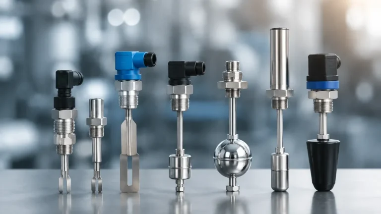
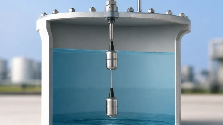
Mechanical float sensors utilize a buoyant object that rises and falls with the water level. In magnetic level gauges, a float containing a magnet moves along a guide tube, actuating reed switches or moving an external indicator. These are often used for Level Switches to provide high-level or low-level alarms.
Comparing Level Switches and Continuous Level Sensors
While continuous sensors provide a 4-20mA or digital signal representing the exact percentage of tank fullness, many water tank applications rely on point level detection.
Level Switches are designed to trigger an action at a specific height. For example, a low-level switch might start a refill pump, while a high-level switch shuts off the inlet valve to prevent overflow. In many industrial water systems, a combination of a continuous sensor (for inventory management) and independent level switches (for safety interlocks) is considered best practice. This redundancy ensures that even if the primary transmitter fails, the level switches provide a mechanical or secondary electronic fail-safe to protect the infrastructure.
Key Evaluation Criteria for Selecting a Level Sensor in a Water Tank
When specifying a level sensor in a water tank, engineers must evaluate several technical parameters to ensure long-term reliability and accuracy.
1. Tank Geometry and Obstructions: Internal structures such as ladders, agitators, or inlet pipes can interfere with non-contact signals (Radar/Ultrasonic). In such cases, a guided wave radar or a hydrostatic sensor may be more appropriate.
2. Water Quality: Pure water, wastewater, and chemically treated water have different dielectric constants and corrosive properties. For corrosive chemical-water mixes, PVDF or PTFE-coated sensors are required.
3. Measurement Range: The height of the tank dictates the sensor's power. Ultrasonic sensors typically cover ranges from 0.5 meters to 15 meters, while radar and hydrostatic sensors can handle much deeper applications, sometimes exceeding 30 meters.
4. Environmental Conditions: If the tank is located outdoors, the sensor must have an appropriate IP rating (typically IP67 or IP68) to withstand rain, humidity, and UV exposure. Temperature compensation is also vital for ultrasonic sensors used in outdoor environments.
5. Output and Integration: Modern industrial systems often require integration via Modbus, HART, or Profibus. Confirming that the sensor's output is compatible with the existing PLC (Programmable Logic Controller) or SCADA system is essential.
Practical Installation Guidelines and Considerations
Proper installation is as critical as selecting the right technology. Poor placement can lead to false readings or premature equipment failure.
* The Dead Zone (Blocking Distance): All non-contact sensors have a "dead zone" directly beneath the transducer where measurement is impossible. For a typical ultrasonic sensor, this might be 0.25m to 0.5m. The sensor must be mounted high enough so that the maximum water level never enters this zone.
* Avoiding the Inlet: Never install a level sensor directly in the path of the falling water from an inlet pipe. The turbulence and air bubbles created by the inflow will cause erratic readings.
* Perpendicular Alignment: For ultrasonic and radar sensors, the transducer face must be perfectly parallel to the water surface. Even a few degrees of tilt can cause the signal to bounce away from the receiver, leading to signal loss.
* Stilling Wells: In tanks with significant agitation or turbulence, a stilling well (a vertical pipe that dampens surface movement) can be used to provide a calm surface for the sensor to measure.
Addressing Common Risks and Environmental Limitations
Engineers should be aware of specific risks that can compromise the performance of a level sensor in a water tank:
* Condensation: In warm water tanks, moisture can bead on the face of an ultrasonic transducer, potentially blocking the signal. Radar sensors with drip-off antenna designs are better suited for these conditions.
* Foam: Heavy foam acts as an insulator for ultrasonic waves, absorbing the sound rather than reflecting it. If foam is a persistent issue, hydrostatic or high-frequency radar sensors are the preferred alternatives.
* Build-up and Scaling: In hard water applications, calcium deposits can build up on contact-type sensors (like floats or probes). Non-contact sensors are generally immune to this, but hydrostatic sensors should be checked periodically for clogging of the sensing diaphragm.
Technology Selection Matrix for Water Applications
| Technology | Typical Accuracy | Best Application | Main Limitation |
| :— | :— | :— | :— |
| Ultrasonic | ±0.25% of range | Standard atmospheric tanks | Affected by foam and wind |
| Radar (80GHz) | ±2 mm | Narrow tanks, steam/vapor | Higher initial cost |
| Hydrostatic | ±0.1% to 0.5% | Deep wells, underground tanks | Sensitive to density changes |
| Float Switches | N/A (Point) | Pump control, overflow alarm | Moving parts can wear/stick |
| Guided Wave Radar | ±3 mm | Small tanks with obstructions | Contact with media required |
Frequently Asked Questions (FAQs)
Q: How often should a level sensor in a water tank be calibrated?
A: Most modern digital sensors are factory-calibrated and require minimal maintenance. However, for critical applications, an annual verification against a manual tape measure is recommended. Hydrostatic sensors may require more frequent zero-point checks if the liquid density varies.
Q: Can one sensor be used for multiple tanks?
A: Generally, each tank requires its own dedicated sensor for real-time monitoring. However, some multi-channel controllers can process signals from several individual sensors, centralizing the data display and control logic.
Q: What is the best way to protect sensors from lightning in outdoor tanks?
A: Outdoor installations should include surge protection devices on the signal loop. Many industrial-grade sensors have built-in surge protection, but external modules provide an extra layer of safety for the PLC electronics.
Q: Is a stilling well necessary for all water tanks?
A: No. Stilling wells are only necessary if there is extreme turbulence, heavy surface foam, or if the tank has many internal obstructions that interfere with a non-contact sensor’s beam.
By understanding these technical nuances, facility managers and engineers can ensure they select a reliable level measurement solution that minimizes maintenance and prevents costly overflows or dry-run conditions in their water storage systems.