Level Sensor Light
Level Sensor Light
In industrial process automation, the term "level sensor light" typically refers to two distinct but related concepts: the visual indicator lights integrated into level measurement devices and the optical sensing technology used to detect the presence or absence of liquid. For plant engineers and maintenance technicians, understanding how these visual signals and light-based sensors function is critical for ensuring operational safety and preventing tank overfills or pump dry-runs.
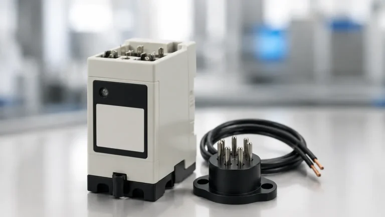
Visual feedback through a level sensor light provides immediate, at-a-glance status updates on the factory floor, allowing operators to verify the state of a vessel without consulting a central control room. Whether it is a simple LED on a compact probe or a high-visibility strobe on a heavy-duty silo switch, these indicators are essential components of modern Level Switches.
Measurement Principles of Level Switches and Indicators
Before selecting a device based on its visual output, it is important to understand the underlying measurement principles that trigger these signals. Level switches act as point-level detectors, providing a binary output (on/off) when a material reaches a specific height.
1. Optical Level Sensing (Sensing with Light)
Optical level sensors utilize the principle of infrared light refraction. The sensor consists of an internal infrared LED and a light receiver. When the sensor tip is in the air, the infrared light reflects inside the prism tip and returns to the receiver. When liquid submerges the tip, the light refracts into the medium, causing the receiver to detect a change in light intensity. This change triggers the switch state and, subsequently, the integrated level sensor light.
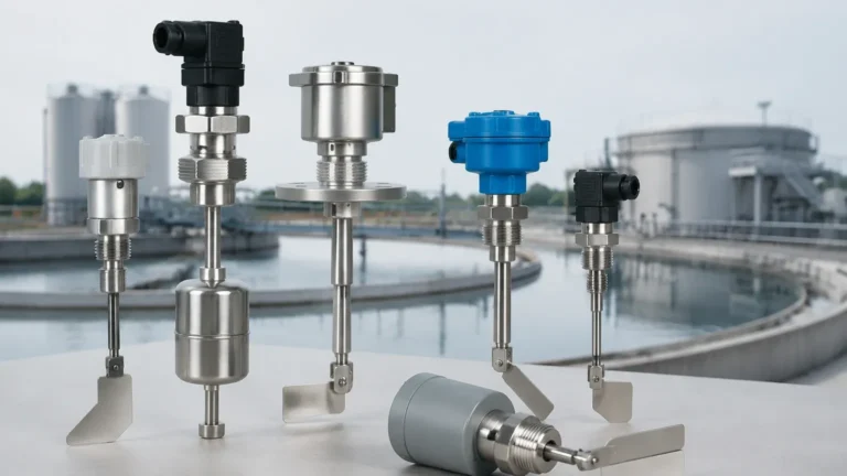
2. Vibrating Tuning Fork Principle
Vibrating level switches use a piezoelectric crystal to energize a tuning fork at its natural frequency. When the fork is covered by liquid or solids, the frequency shifts or the amplitude drops. The electronics detect this change and switch the output. Most high-quality tuning fork switches include a level sensor light (LED) at the base of the housing to indicate whether the unit is powered and whether the alarm state is active.
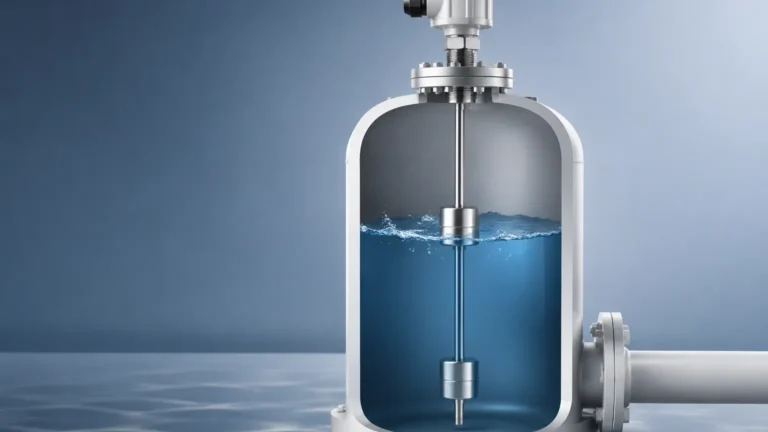
3. Float and Magnetic Principles
Mechanical float switches use a buoyant magnet that moves with the liquid level to actuate a reed switch. While the primary mechanism is mechanical, modern industrial versions often include an external junction box equipped with a level sensor light to provide local visual confirmation of the reed switch position.
The Role of the Integrated Level Sensor Light
In a B2B industrial environment, the "light" on a sensor serves several functional purposes beyond simple status indication:
* Status Verification: A green light typically indicates that the device is powered and the level is within the normal range. A change to red or amber indicates a high or low-level alarm.
* Diagnostic Signaling: Advanced sensors use flashing patterns in the level sensor light to communicate specific fault codes, such as a covered probe during startup, internal electronic failure, or excessive buildup on the sensing element.
* Calibration Assistance: During the setup of capacitive or ultrasonic switches, the integrated light often flickers to indicate the "switch point" has been reached, allowing for precise mechanical adjustment without needing a multimeter.
Technical Comparison of Level Switch Technologies
When choosing between different technologies that utilize a level sensor light, engineers must consider the media properties and environmental conditions. The following table provides a comparison of common point-level detection methods.
| Technology | Media Type | Sensitivity to Foam/Vapor | Integrated Light Function | Best Use Case |
| :— | :— | :— | :— | :— |
| Optical | Clear Liquids | High (Sensitive) | State & Power Indication | Leak detection in clean pipes |
| Tuning Fork | Liquids/Solids | Low (Robust) | Alarm & Diagnostic LED | General purpose tank level |
| Capacitive | Conductive/Non-conductive | Moderate | Sensitivity/Calibration Light | Corrosive chemical storage |
| Float | Clean Liquids | None | Local Status LED | Simple water sumps |
| Ultrasonic | Non-foaming Liquids | High (Sensitive) | Echo Strength Indicator | Non-contact point detection |
Application Considerations for Optical Level Sensors
Because a "level sensor light" often refers to optical sensors, it is vital to recognize their specific application boundaries. Optical sensors are highly valued for their compact size and lack of moving parts, but they have limitations:
* Coating and Turbidity: If the liquid is extremely viscous and leaves a thick film on the prism, the light may refract incorrectly, leading to a false positive. Similarly, highly turbulent liquids can cause "chatter" in the signal light.
* Ambient Light Interference: In outdoor installations or near high-intensity industrial lighting, unshielded optical sensors may experience interference. Most industrial-grade optical level switches use modulated infrared light to filter out ambient noise.
* Pressure and Temperature: Optical prisms are typically made of polysulfone or glass. Engineers must ensure the material is compatible with the process temperature (often up to 125°C / 257°F) and pressure (up to 50 bar / 725 psi).
Installation and Wiring Guidelines
Proper installation ensures that the level sensor light is both functional and visible to operators. Follow these best practices during the integration phase:
Orientation and Visibility
When installing a switch with a built-in indicator, the housing should be rotated so the LED is visible from the primary walkway. Many industrial switches allow the housing to be rotated 270° to 360° after the process connection is tightened. For optical sensors, horizontal installation is generally preferred to allow liquid to drain off the prism tip effectively.
Wiring for Signal Output
Most level switches with integrated lights utilize a 3-wire DC circuit (PNP or NPN).
1. Brown Wire: Positive (+) Power Supply (typically 10-30V DC).
2. Blue Wire: Negative (-) Power Supply.
3. Black Wire: Output Signal.
In a PNP configuration, the load is connected between the black wire and the negative terminal. When the level is detected, the level sensor light illuminates, and the black wire provides a high-voltage signal to the PLC (Programmable Logic Controller).
Cable Protection
In environments where the level sensor light is exposed to wash-downs (IP67 or IP69K environments), ensure that the cable entry points are sealed with appropriate glands. Moisture ingress into the housing is the leading cause of LED failure and erratic switching behavior.
Limitations and Environmental Factors
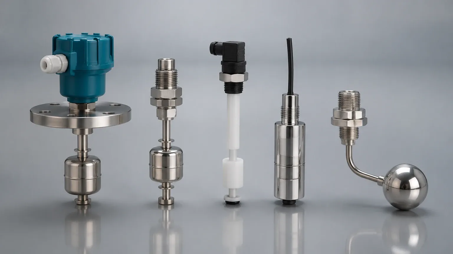
While visual indicators are helpful, they should not be the sole method of monitoring in critical safety applications.
* Distance: Standard LEDs on level switches are usually only visible from 5 to 10 meters (16 to 32 feet). For large-scale facilities, secondary remote indicator lights or tower lights should be wired to the switch output.
* Bubbles and Foam: In fermentation or chemical mixing tanks, foam can be mistaken for liquid by optical and ultrasonic sensors. In these cases, a tuning fork or displacement-based switch is more reliable.
* Power Consumption: While negligible in most factory settings, in remote solar-powered installations, the continuous operation of a level sensor light can contribute to battery drain. Some low-power models allow the LED to be disabled via an internal jumper.
Maintenance and Troubleshooting
To ensure the longevity of the level sensor light and the accuracy of the measurement, a routine maintenance schedule should be implemented.
1. Prism Cleaning: For optical sensors, wipe the sensing tip monthly to remove any mineral deposits or bio-film. Use a soft cloth to avoid scratching the prism.
2. Housing Inspection: Check for cracks in the transparent LED cover. In chemical plants, plastic covers can become opaque over time due to chemical vapors, obscuring the light.
3. Voltage Check: If the level sensor light is dim or flickering, check the supply voltage. Most industrial switches require a stable 24V DC source; voltage drops over long cable runs can cause the electronics to malfunction.
Frequently Asked Questions (FAQ)
Q: Can a level sensor light be used in hazardous areas?
A: Yes, but the device must be ATEX or IECEx certified. In these cases, the light is usually housed behind a thick explosion-proof glass window or is part of an intrinsically safe circuit with a limited energy output.
Q: Why is my optical level sensor light on when the tank is empty?
A: This is often caused by "bridging" or coating on the sensor tip. If a droplet of liquid remains on the prism, it continues to refract light as if submerged. Cleaning the tip or mounting the sensor at a slight downward angle can resolve this.
Q: What is the difference between an NPN and a PNP level sensor light?
A: This refers to the polarity of the switching output. PNP switches "push" the voltage to the load, while NPN switches "pull" the load to the ground. The integrated light will function the same way in both, but the wiring to your PLC must match the sensor type.
Q: Can I replace the LED if the level sensor light burns out?
A: In most modern potted or sealed industrial sensors, the LED is integrated into the circuit board and is not field-replaceable. If the light fails, the entire sensor head usually needs to be replaced to maintain the environmental seal.
Conclusion
The integration of a level sensor light into industrial instrumentation is a simple yet powerful tool for process transparency. By combining robust sensing technologies—such as optical, tuning fork, or float mechanisms—with clear visual feedback, facilities can maintain higher safety standards and operational efficiency. When selecting your next set of Level Switches, consider not only the chemical compatibility and pressure ratings but also the visibility and diagnostic capabilities of the integrated signaling system. Proper selection and installation ensure that your "level sensor light" remains a reliable sentinel for your industrial liquid and solid storage systems.