Level Switch Nc Symbol
Level Switch Nc Symbol
In the field of industrial automation and process control, the ability to accurately interpret electrical schematics is fundamental to ensuring system safety and operational efficiency. Among the various components found in these diagrams, level switches play a critical role in monitoring the contents of tanks, silos, and sumps. Understanding the level switch nc symbol (Normally Closed) is essential for engineers and technicians tasked with designing, installing, or maintaining level control systems. This guide provides a comprehensive technical overview of level switch symbols, their underlying measurement principles, and practical considerations for industrial applications.
Introduction to Level Switch Electrical Schematics
Electrical symbols serve as a universal language in engineering, allowing complex systems to be documented and communicated clearly. For Level Switches, the symbol must convey two primary pieces of information: the physical nature of the sensor (e.g., float, capacitive, or ultrasonic) and the electrical state of the contacts in their resting position.
The term "Normally Closed" (NC) refers to the state of the switch when it is not being acted upon by the process variable—in this case, the liquid or solid level. In a schematic, the level switch nc symbol typically depicts a contact that is physically touching its terminal, indicating a complete electrical circuit. When the level reaches the switch's actuation point, the contact moves to the "open" position, breaking the circuit.
Core Principles of Level Switch Operation
Before selecting a switch based on its electrical symbol, it is necessary to understand how different technologies achieve the physical actuation required to change the switch state. Welk offers several distinct technologies, each suited to specific process conditions.
1. Float Level Switches
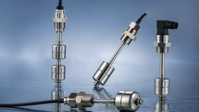
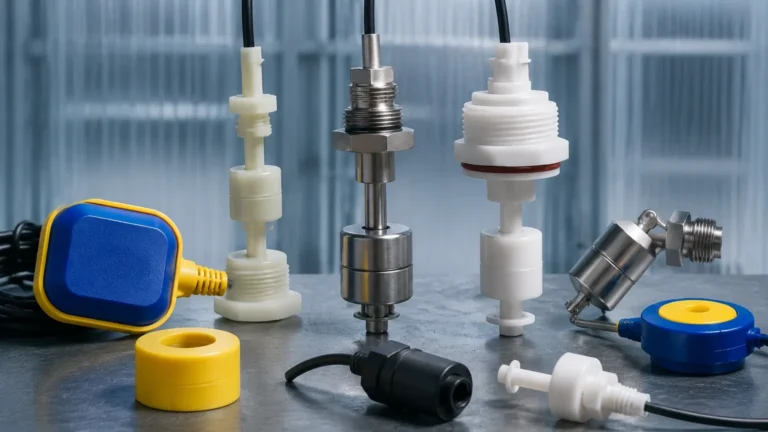
Float switches operate on the principle of buoyancy. A float containing a magnet moves with the liquid level. When the float reaches a predetermined point, the magnetic field actuates a reed switch or a microswitch. In an NC configuration, the reed switch is closed when the float is at its "normal" (usually low) position and opens as the float rises.
2. Tuning Fork (Vibrating) Level Switches
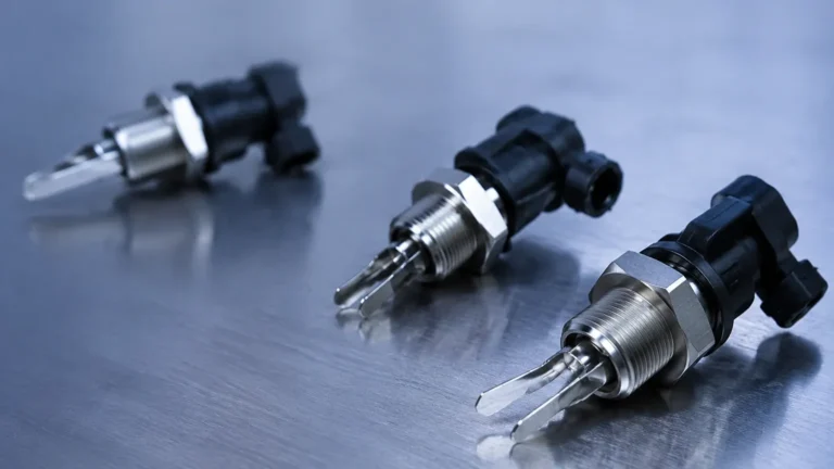
The sensor consists of two tines that vibrate at their natural resonant frequency in air. When the tines are covered by a liquid or solid, the frequency shifts or the vibration is damped. An electronic circuit detects this change and toggles the output. These are highly reliable for preventing overfill in turbulent environments.
3. Capacitive Level Switches
Capacitive sensors measure the change in capacitance between a probe and the tank wall (or a reference probe). As the medium displaces air around the probe, the dielectric constant changes, triggering the switch. These are ideal for non-conductive liquids and bulk solids.
4. Hydrostatic and Radar Switches
While often used for continuous measurement, these devices can be configured with switching outputs. They use pressure or microwave time-of-flight to determine level, providing a non-contact or high-durability option for aggressive chemicals.
Decoding the Level Switch NC Symbol and Logic
The level switch nc symbol in a P&ID (Piping and Instrumentation Diagram) or an electrical ladder logic diagram is often represented by a standard switch contact with a small "flag" or "float" icon attached.
Standard Representation
* NC (Normally Closed): The contact is drawn touching the line, indicating continuity in the shelf state.
* NO (Normally Open): The contact is drawn away from the line, indicating a broken circuit in the shelf state.
Fail-Safe Logic
A critical reason for choosing an NC symbol in design is "fail-safe" operation. In a high-level alarm application, using an NC switch means the circuit is closed when the tank is not full. If a wire breaks or power is lost to the sensor, the circuit opens. The control system interprets this open circuit as a high-level alarm (or a fault), prompting an immediate stop to filling. This prevents accidental overflows that might occur if a Normally Open switch failed to close due to a broken wire.
Technical Selection Criteria for Industrial Level Switches
Choosing the correct switch involves more than just identifying the NC or NO requirement. Engineers must evaluate the chemical compatibility, temperature, and pressure of the process.
| Technology | Best For | Temperature Range | Pressure Limit | Viscosity Handling |
| :— | :— | :— | :— | :— |
| Float | Clean liquids, water | Up to 150°C | Up to 40 bar | Low |
| Tuning Fork | Powders, liquids, oils | -50°C to 250°C | Up to 64 bar | Medium |
| Capacitive | Corrosive chemicals | Up to 200°C | Up to 100 bar | Low to High |
| Hydrostatic | Deep tanks, wastewater | -20°C to 80°C | N/A (Submersible) | Medium |
When reviewing Level Switches, consider the following electrical parameters:
* Switching Voltage: Ensure the switch can handle the control circuit voltage (typically 24V DC or 110V/220V AC).
* Switching Current: The maximum amperage the contacts can break without welding together.
* Hysteresis: The difference between the point where the switch turns on and where it turns off, preventing "chattering" in turbulent liquids.
Installation Guidelines and Wiring Best Practices
Correct installation is as vital as correct symbol interpretation. Even a perfectly specified NC switch will fail if installed incorrectly.
1. Orientation: Float switches are often orientation-sensitive. A switch designed for vertical installation may not function if mounted horizontally unless specifically rated for it.
2. Turbulence Protection: In tanks with agitators or high-flow inlets, use stilling wells to prevent mechanical fatigue of the switch components and to avoid false triggers.
3. Wiring the NC Circuit: When wiring a level switch nc symbol in a control panel, always use shielded cables if the run is long to prevent electromagnetic interference (EMI) from triggering false signals.
4. Sealing: Ensure the cable entry points are sealed with appropriate glands (IP65/IP67/IP68) to prevent moisture ingress, which is a leading cause of premature switch failure.
Metric Installation Constants
* Minimum Distance from Wall: Typically 50 mm to 100 mm to avoid interference.
* Thread Sizes: Common industrial standards include G1/2", G1", or NPT equivalents.
* Cable Lengths: Standard factory leads are often 2 meters, but customized lengths are available for deep well applications.
Limitations and Operational Risks
While NC configurations are preferred for many safety loops, they are not without limitations:
* Contact Pitting: In mechanical switches (floats), repeated switching of inductive loads can cause arcing and pitting of the contacts, eventually leading to a permanent "open" or "closed" failure regardless of level.
* Coating and Buildup: For tuning fork and capacitive switches, heavy material buildup can "trick" the sensor into thinking it is covered, even when the level has dropped. This is particularly risky in NC circuits used for low-level protection.
* Specific Gravity Changes: Float-based switches depend on the density of the liquid. If the process fluid changes (e.g., from water to a light oil), the float may no longer provide enough buoyancy to actuate the switch correctly.
Frequently Asked Questions (FAQs)
Q: How do I tell if my switch is NC or NO if the label is missing?
A: Use a multimeter set to the continuity or resistance (Ohms) setting. With the switch in its "rest" position (e.g., held in the air as it would be in an empty tank), check the terminals. If the meter beeps or shows near-zero ohms, it is NC. If it shows infinite resistance, it is NO.
Q: Can I change an NC switch to an NO switch?
A: Many industrial level switches, especially float types, allow the user to flip the float upside down to reverse the logic. For electronic switches (tuning fork or capacitive), there is usually a DIP switch or a wiring terminal change (Common to NC vs. Common to NO) that allows for field reversal.
Q: What does the 'NC' symbol look like in a PLC program?
A: In Ladder Logic, an NC contact is represented by two parallel vertical lines with a diagonal slash through them (examine the Examine If Open or XIO instruction). This instruction is true if the physical input is de-energized.
Q: Is the level switch nc symbol the same globally?
A: While IEC (International Electrotechnical Commission) and ANSI (American National Standards Institute) symbols differ slightly in appearance, the fundamental representation of a closed contact for NC remains consistent. IEC symbols tend to be more rectangular, while ANSI symbols use the traditional "switch" arm.
By carefully matching the physical requirements of the application with the correct electrical configuration and understanding the level switch nc symbol, engineers can design robust systems that minimize downtime and maximize safety. For detailed technical specifications and to explore various switching technologies, professionals should Review product options and application support to ensure the selected instrument meets the specific demands of their industrial environment.