Level Switch 1 2
Level Switch 1 2
In the realm of industrial process control, point level detection remains a critical requirement for safety, efficiency, and automation. Among the various specifications encountered by instrumentation engineers, the "level switch 1 2" designation typically refers to one of two critical technical parameters: a 1/2-inch (DN15) process connection size or a specific electrical configuration, such as a Single Pole Double Throw (SPDT) contact arrangement.
Choosing the correct Level Switches involves more than just matching thread sizes. It requires a deep understanding of the medium being measured, the environmental conditions of the vessel, and the mechanical constraints of the installation site. This guide provides a comprehensive technical overview of level switches with 1/2-inch connections, their operating principles, and selection criteria for industrial applications.
Understanding the Fundamentals of Level Switches
A level switch is a sensor designed to detect the presence or absence of a substance (liquid, powder, or granulated solid) at a specific height within a container. Unlike continuous level transmitters that provide a constant output of the current level, a level switch acts as a binary trigger. When the material reaches the sensor's position, the switch changes state, sending a signal to a control system (PLC), alarm, or pump.
The "1 2" specification often appears in procurement documents to denote a 1/2" NPT or G thread. This size is particularly common in compact industrial equipment, hydraulic reservoirs, and small chemical dosing tanks where space is limited but robust mounting is required.
Common Measurement Principles for 1/2-Inch Level Switches
Before selecting a level switch, it is essential to understand the physics behind the detection. Different technologies are suited to different media properties such as viscosity, conductivity, and dielectric constant.
1. Float Level Switches (Mechanical)
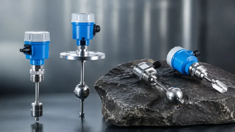
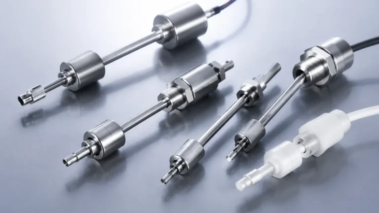
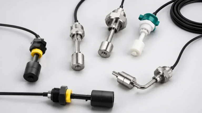
Float switches utilize buoyancy. A float containing a magnet moves with the liquid level along a stem. When the float reaches a predetermined point, the internal magnet actuates a reed switch.
* Advantages: Simple, requires no power to operate the switch itself, and cost-effective.
* Limitations: Moving parts can get stuck in viscous or scaling liquids. Not suitable for liquids containing magnetic particles.
2. Vibrating Tuning Fork Switches (Electronic)
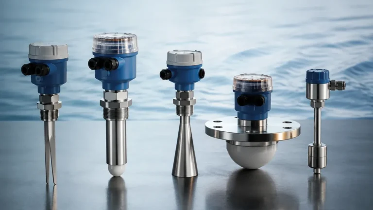
The sensor consists of two tines that vibrate at their natural resonant frequency in air. When the tines are submerged in a liquid or solid, the frequency changes. This shift is detected by the internal electronics and converted into a switching signal.
* Advantages: Highly reliable, unaffected by foam, bubbles, or turbulence.
* Limitations: Generally more expensive than basic floats; requires a power supply.
3. Capacitive Level Switches
These sensors measure the change in electrical capacitance between the sensor probe and the tank wall (or a reference electrode). As the medium covers the probe, the dielectric constant changes, triggering the switch.
* Advantages: No moving parts; can be used for both liquids and solids.
* Limitations: Sensitive to material build-up on the probe, though modern versions include "active shield" technology to ignore coating.
4. Optoelectronic Level Switches
These use an infrared LED and a light receiver. In air, the light is reflected within a prism at the sensor tip. When liquid covers the prism, the light is refracted into the liquid, and the receiver detects the loss of signal.
* Advantages: Extremely compact (ideal for 1/2" connections), very fast response time.
* Limitations: Not suitable for liquids that leave a thick film or coating on the prism.
The Significance of the 1/2-Inch Process Connection
The physical interface between the sensor and the vessel is a critical failure point if not specified correctly. In the context of a level switch 1 2, the 1/2-inch size is standard across several thread types:
* 1/2" NPT (National Pipe Tapered): Common in North America. It creates a seal through thread interference and usually requires PTFE tape or pipe dope.
* 1/2" G (BSPP – British Standard Pipe Parallel): Common in Europe and Asia. It relies on an O-ring or a flat gasket at the base of the thread to create a seal.
* Metric M20x1.5: Occasionally used in specific European machinery, though 1/2" G is more prevalent.
Using a 1/2-inch connection allows for a balance between mechanical strength and a small footprint. It is large enough to house robust sensing elements like tuning forks but small enough to be installed in tight manifolds or small-diameter bypass pipes.
Selection Criteria and Technical Comparison
When specifying a level switch 1 2 for a project, engineers should use the following comparison table to narrow down the technology based on application needs.
| Feature | Float Switch | Vibrating Fork | Capacitance | Optoelectronic |
| :— | :— | :— | :— | :— |
| Media Type | Clean Liquids | Liquids/Solids | Liquids/Solids | Clean Liquids |
| Viscosity Limit | Low (< 500 cP) | Medium (< 10,000 cP) | High | Low |
| Pressure Range | Up to 40 bar | Up to 64 bar | Up to 100 bar | Up to 50 bar |
| Temp. Range | -20°C to 120°C | -50°C to 150°C | -40°C to 200°C | -20°C to 100°C |
| Moving Parts | Yes | No | No | No |
| Mounting | Vertical/Horizontal | Any Orientation | Any Orientation | Any Orientation |
Installation and Mounting Guidelines
Proper installation is paramount to ensure the longevity of the level switch 1 2 and the accuracy of the signal.
Orientation Matters
* Top Mounting: Usually reserved for float switches with long stems or ultrasonic switches. Ensure the "dead zone" (the area where the sensor cannot detect) is accounted for in the tank's overflow calculations.
* Side Mounting: Common for 1/2" NPT tuning forks or optical sensors. The sensor should be installed slightly angled or with the tines oriented vertically (for forks) to prevent liquid from pooling on the sensor surface, which could cause false triggers.
Sealing and Torque
For 1/2" NPT threads, over-tightening can crack the housing of plastic sensors or damage the threads of thin-walled tanks. Always follow the manufacturer's torque specifications. For G 1/2" threads, ensure the sealing washer is compatible with the process medium (e.g., Viton for oils, EPDM for water).
Wiring and Electrical Safety
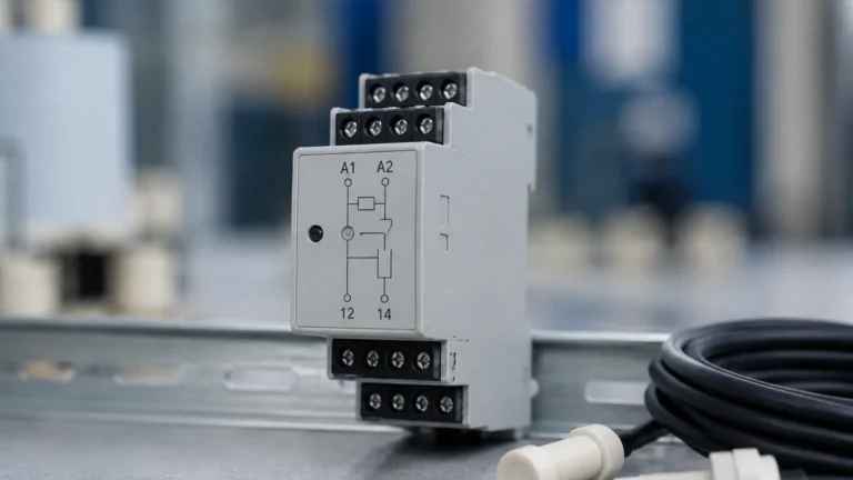
The "1 2" in a level switch context may also refer to the electrical output. Most industrial switches provide an SPDT (Single Pole Double Throw) output, which includes:
1. Common (C)
2. Normally Open (NO)
3. Normally Closed (NC)
This allows the user to choose whether the circuit closes or opens when the level is reached. For safety-critical applications, such as high-level alarms, a "Normally Closed" configuration is preferred so that a broken wire will trigger a fail-safe alarm.

Application Scenarios in Industrial Automation
Water and Wastewater Treatment
In chemical dosing systems, 1/2-inch level switches are used to prevent pumps from running dry. Plastic (PP or PVDF) float or ultrasonic switches are preferred here due to their resistance to corrosive chemicals like sodium hypochlorite.
Hydraulic Power Units (HPUs)
Oil reservoirs in hydraulic systems require constant monitoring. A compact 1/2" NPT vibrating fork or a rugged stainless steel float switch ensures that the oil level does not drop below the suction line, preventing pump cavitation and system failure.
Food and Beverage Processing
Small-scale brewing or dairy equipment often uses 1/2-inch G thread connections. In these environments, the sensor must be made of 316L stainless steel and feature a hygienic design to prevent bacterial growth in the threads.
Limitations and Prohibitions
While versatile, the level switch 1 2 has specific limitations:
* Turbulence: Mechanical float switches can bounce in turbulent tanks, leading to "chatter" in the electrical relay. In such cases, electronic switches with a programmable delay are required.
* Coating and Buoyancy: In wastewater applications with high grease content, floats may become heavy and sink, or tuning forks may become bridged with debris. Regular inspection is necessary.
* Pressure Spikes: Ensure the selected switch is rated for the maximum possible system pressure, including potential water hammer effects, which can exceed 20 bar (290 psi) in some pipelines.
Maintenance and Troubleshooting
To maintain the reliability of your level measurement system, implement a routine maintenance schedule:
1. Visual Inspection: Check for leaks around the 1/2-inch thread and signs of corrosion on the sensor body.
2. Cleaning: For capacitive and optical sensors, ensure the sensing face is free of film or scale. Use a soft cloth and compatible solvent.
3. Functional Test: Manually actuate the switch (if possible) or raise the liquid level to verify that the control system receives the correct signal.
If a switch fails to trigger, first check the power supply (for electronic types) and then inspect for mechanical obstructions. For reed-switch based floats, a common failure mode is contact welding caused by high inrush currents; always use an intermediate relay if switching heavy inductive loads.
Frequently Asked Questions (FAQ)
Q: Can I use a 1/2" NPT level switch in a 1/2" G threaded hole?
A: No. While they appear similar, the thread pitches and shapes are different. Forcing an NPT male into a G female will damage the threads and will not create a pressure-tight seal.
Q: What is the best material for a level switch 1 2 in a sulfuric acid tank?
A: For concentrated acids, PTFE or PVDF are the preferred materials. Stainless steel 316L may be used for very low concentrations, but plastic is generally safer for longevity.
Q: How do I prevent false triggers from foam?
A: Vibrating tuning forks are generally the best choice for ignoring foam. Optical and ultrasonic switches may struggle as they might see the top of the foam as the liquid level.
Q: Does a level switch 1 2 require calibration?
A: Most point level switches are factory-set and do not require field calibration. However, some capacitive switches have a sensitivity adjustment screw to fine-tune the detection for specific media densities.
For more detailed technical specifications and to explore various models, you can Review product options and application support to find the ideal solution for your specific process requirements.