Level Switch Connection Diagram
Level Switch Connection Diagram
In industrial process control, level switches serve as critical components for overfill protection, pump control, and dry-run prevention. While the mechanical installation of these devices is straightforward, the electrical integration—guided by the level switch connection diagram—is where system reliability is established. A correctly interpreted wiring scheme ensures that the instrument communicates accurately with Programmable Logic Controllers (PLCs), Distributed Control Systems (DCS), or direct motor starters.
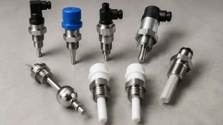
As a professional manufacturer, Welk provides a range of Level Switches designed for diverse industrial environments. Understanding the underlying measurement principles and the corresponding electrical configurations is essential for any engineering or maintenance team.
Measurement Principles of Level Switches
Before analyzing a level switch connection diagram, it is necessary to understand how the specific technology detects the presence or absence of a medium. The wiring requirements often vary based on the sensing technology and the power consumption of the internal electronics.
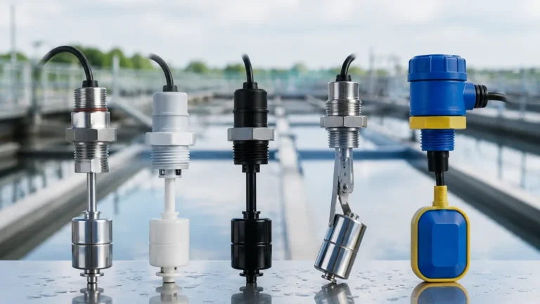
Float Level Switches
Float switches operate on the principle of buoyancy. A float containing a permanent magnet moves with the liquid level. When the float reaches a predetermined point, the magnetic field actuates a hermetically sealed reed switch or a microswitch. These are typically passive devices (unless they include integrated transmitters), meaning they do not require external power to operate the sensing element itself, though they require power for the signal loop.
Vibrating Tuning Fork Switches
The tuning fork switch uses piezoelectric crystals to vibrate a metal fork at its natural resonance frequency (typically around 1,200 Hz to 1,400 Hz). When the fork is submerged in liquid or covered by solids, the frequency shifts or the vibration is dampened. The electronics detect this change and switch the output. These devices require a continuous power supply to maintain the vibration.
Capacitance Level Switches
These switches measure the change in electrical capacitance between the sensing probe and the tank wall (or a reference electrode). As the medium displaces air, the dielectric constant changes, altering the capacitance. The internal circuitry converts this change into a switching signal. Like tuning fork switches, these require an active power source.
Ultrasonic and Optical Switches
Ultrasonic switches use high-frequency sound waves to detect the interface, while optical switches use infrared light refraction. Both technologies rely on solid-state electronics and typically offer PNP/NPN or relay outputs, requiring specific attention to the level switch connection diagram to avoid polarity errors.
Decoding the Level Switch Connection Diagram
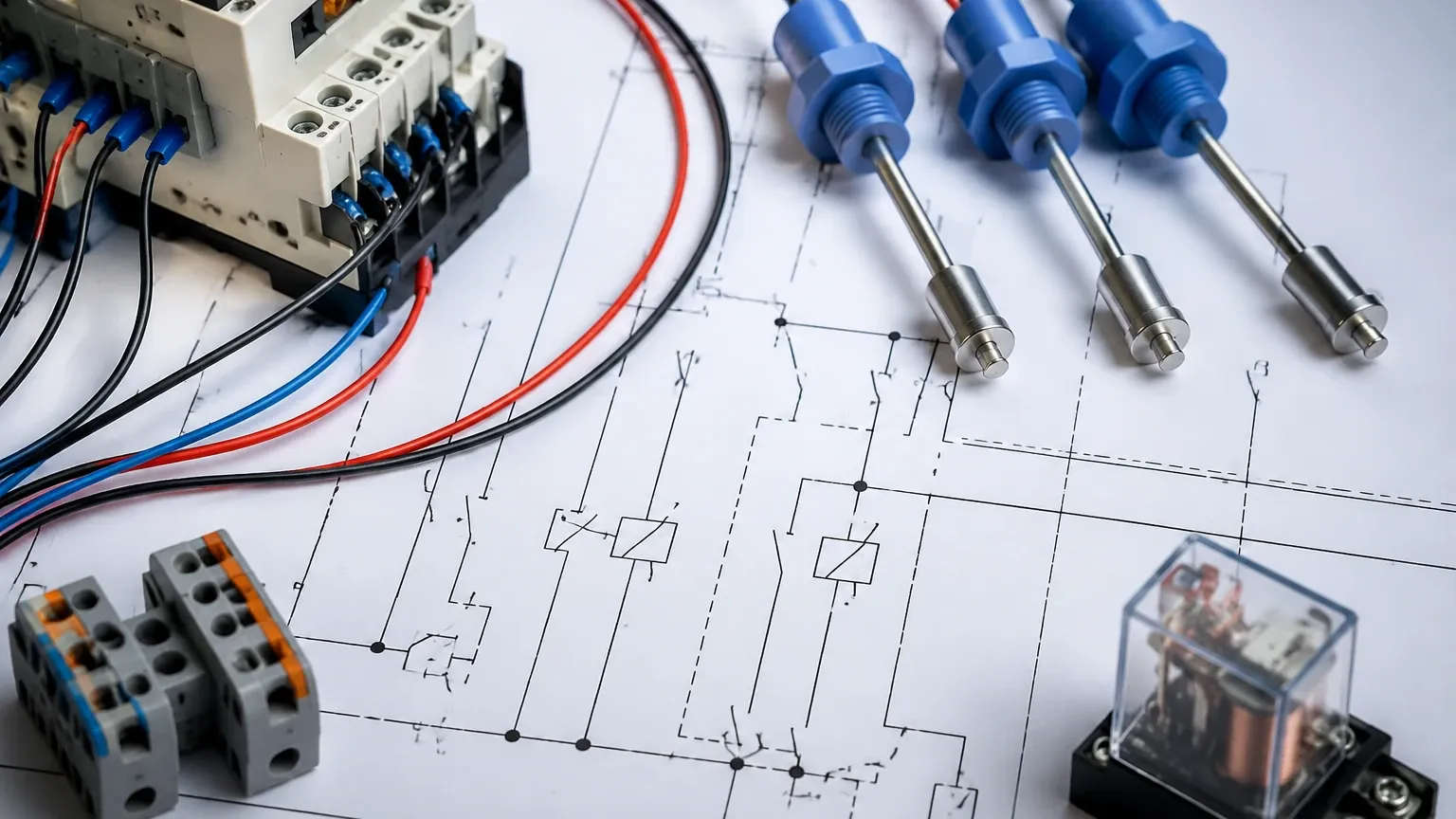
A level switch connection diagram is a schematic representation of the electrical terminals and the internal switching logic. It provides three primary pieces of information: the power supply requirements, the output configuration, and the fail-safe settings.
1. Power Supply Terminals
Most industrial level switches operate on either 24V DC or universal AC/DC power (e.g., 20V to 250V AC/DC).
- DC Wiring: Usually labeled as V+ and V- (or L+ and M).
- AC Wiring: Labeled as L (Line) and N (Neutral).
- Grounding: A dedicated PE (Protective Earth) terminal is essential for metal housings to ensure safety and EMI shielding.
2. Output Configurations
The output is where the switch interacts with the external control circuit. The most common types found on a level switch connection diagram include:
* Relay Output (SPDT/DPDT): A Single Pole Double Throw (SPDT) relay provides three terminals: Common (COM), Normally Open (NO), and Normally Closed (NC). A Double Pole (DPDT) provides two sets of these contacts for redundant signaling.
* Transistor Output (PNP/NPN): Common in DC systems, these are solid-state switches. PNP switches the positive load, while NPN switches the negative load.
* Two-Wire (Load Powered): The switch is wired in series with the load. It draws a small leakage current to power itself when "off" and allows full current when "on."
* NAMUR: A current-coded signal (typically 1mA vs. 2.2mA) used in intrinsically safe applications.
3. Fail-Safe Logic
Fail-safe settings determine the state of the switch in the event of a power failure.
- Fail-Safe High (FSH): The relay is energized when the level is low and de-energizes when the level is high or power is lost. This is used for overfill prevention.
- Fail-Safe Low (FSL): The relay is energized when the level is high and de-energizes when the level is low or power is lost. This is used for dry-run protection.
Practical Selection Table for Electrical Interfaces
| Output Type | Best For | Advantages | Limitations |
| :— | :— | :— | :— |
| Relay (SPDT) | High power loads, AC/DC isolation | Simple to wire, handles high current | Mechanical wear, slower response |
| PNP/NPN | High-speed PLC inputs | No moving parts, very long life | DC only, limited current capacity |
| 2-Wire DC | Reducing cabling costs | Only two wires needed | Requires minimum load current |
| NAMUR | Hazardous areas | Intrinsically safe, detects wire breaks | Requires specialized barrier/amplifier |
Installation Considerations and Safety
When implementing the wiring as per the level switch connection diagram, several practical factors must be addressed to ensure long-term reliability.
Cable Selection and Entry
Use shielded cables for electronic switches (tuning fork, capacitance) to prevent interference from nearby VFDs or heavy motors. Ensure that cable glands are tightened to maintain the IP65/IP67/IP68 rating. A "drip loop" should always be formed before the cable enters the gland to prevent moisture from tracking along the cable into the housing.
Terminal Torque and Wire Ferrules
Loose connections are a leading cause of intermittent failures. Use wire ferrules for stranded copper wire to ensure a secure fit in screw terminals. Follow the manufacturer's torque specifications, typically ranging from 0.5 to 0.8 Nm for standard industrial terminal blocks.
Hazardous Area Compliance
If the level switch is installed in a zone with explosive gases or dust, the connection diagram will often include an Intrinsic Safety (IS) barrier. The wiring between the switch and the barrier must be kept separate from non-IS wiring to prevent energy surges from bypassing the protection.
Common Risks and Troubleshooting
Failure to follow the level switch connection diagram accurately can lead to several common issues:
1. Polarity Reversal: In DC PNP/NPN switches, reversing the V+ and V- can destroy the output transistor if the device lacks reverse polarity protection.
2. Inductive Load Spikes: When a relay output drives an inductive load (like a solenoid valve or a large contactor), back-EMF can weld the relay contacts. Installing a snubber circuit (RC for AC, diode for DC) across the load is recommended.
3. Incorrect Fail-Safe Setting: If the switch is wired for high-level alarm but the internal jumper is set to FSL, the system will indicate a fault when the tank is actually safe, leading to unnecessary downtime.
4. Voltage Drop: In long cable runs (over 500 meters), the voltage drop may cause electronic switches to malfunction. Ensure the supply voltage at the instrument terminals is within the specified range (e.g., 18-30V DC).
Frequently Asked Questions (FAQ)
Q: Can I use a single level switch to start and stop a pump?
A: A single switch can only provide one trigger point. To implement a start/stop cycle (hysteresis), you typically need two switches (high and low) or a switch with a built-in adjustable differential, or a controller that latches the relay state between two points.
Q: What is the difference between NO and NC on the diagram?
A: "Normally Open" (NO) means the circuit is open when the switch is in its "shelf state" (usually meaning no material is present and the device is powered). "Normally Closed" (NC) means the circuit is closed in that same state. Note that the "normal" state can change depending on whether the manufacturer defines it as the "unpowered" or "powered but inactive" state.
Q: Why does my level switch connection diagram show five terminals for a relay?
A: This usually indicates a DPDT (Double Pole Double Throw) relay, which allows you to switch two independent circuits (e.g., one for a local alarm lamp and one for a PLC input) simultaneously.
Q: How do I wire a switch for a high-temperature application?
A: The wiring remains the same as per the diagram, but you must use high-temperature rated cabling (e.g., PTFE or silicone jacketed) and ensure the electronics housing is separated from the process heat via an extension neck.
Conclusion
Correctly applying a level switch connection diagram is the final, crucial step in an instrumentation project. By understanding the measurement principle—whether it is the mechanical movement of a float or the electronic resonance of a tuning fork—engineers can better interpret the wiring requirements. Always verify the power supply, output type, and fail-safe logic before commissioning to ensure the safety and efficiency of your industrial process.
For specific technical data sheets and detailed wiring schematics for various industrial applications, Review product options and application support to find the right solution for your facility's requirements.