Level Switch Connection
Level Switch Connection
In industrial automation and process control, the reliability of a point-level detection system depends heavily on the integrity of the level switch connection. This term encompasses two critical interfaces: the mechanical connection that secures the sensor to the vessel and the electrical connection that integrates the device into the control logic (PLC, DCS, or alarm panel).
Choosing the correct level switch connection is not merely a matter of physical fit; it involves evaluating pressure ratings, material compatibility, and signal transmission requirements. A failure in either the mechanical or electrical interface can lead to leakage, false readings, or catastrophic overfills. This guide provides a technical overview of how to select, install, and maintain these connections for optimal performance.
Understanding Level Switch Operating Principles
Before determining the appropriate connection type, it is essential to understand the measurement principle of the device. Different technologies impose different physical and electrical requirements on the connection.
Float Level Switches
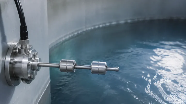
These devices operate on the principle of buoyancy. A float containing a magnet moves with the liquid level, triggering a reed switch located inside the stem. The mechanical connection must allow the float to move freely without hitting the vessel walls. Electrically, these are typically simple "dry contact" devices.
Vibrating Tuning Fork Switches
A piezoelectric crystal vibrates a fork at its natural frequency. When the fork is immersed in a medium, the frequency changes, which is detected by the electronics. These require a robust mechanical level switch connection to withstand the vibration and often use 3-wire or relay outputs.
Capacitive Level Switches
These sensors measure the change in capacitance between the probe and the tank wall (or a reference electrode). The connection must ensure a stable electrical ground to the vessel, especially in non-metallic tanks where a ground rod might be required.
Ultrasonic and Radar Switches
Non-contact or contact-based wave-emitting sensors require precise orientation. The connection must ensure the sensor is perpendicular to the liquid surface to avoid signal scattering.
Mechanical Level Switch Connection Types
The mechanical interface ensures the Level Switches are securely mounted and leak-proof. The choice depends on the internal pressure of the tank, the corrosiveness of the medium, and industry-specific standards.
1. Threaded Connections
Threaded connections are the most common for small-to-medium sized vessels. They are cost-effective and easy to install.
* NPT (National Pipe Taper): Common in North America, these threads create a seal by wedging the threads together. They often require PTFE tape or sealant.
* G Threads (BSP/ISO 228): Parallel threads common in Europe and Asia. These rely on an O-ring or a flat gasket at the base of the thread to create a seal.
* Sizes: Typically range from 1/2" to 2" (15 mm to 50 mm).
2. Flanged Connections
Flanges are preferred for high-pressure applications, large tanks, and processes requiring frequent maintenance. They provide a more robust seal and are easier to align than threaded versions.
* Standards: Common standards include ANSI/ASME B16.5 (Class 150, 300, 600) and DIN/EN 1092-1 (PN16, PN40).
* Materials: Usually carbon steel or 316 stainless steel, matched to the vessel material to prevent galvanic corrosion.
3. Sanitary (Tri-Clamp) Connections
In the food, beverage, and pharmaceutical industries, connections must be "hygienic." Tri-clamp connections eliminate crevices where bacteria can grow. They allow for quick disassembly for cleaning (CIP/SIP processes).
Electrical Wiring and Signal Output Configurations
The electrical level switch connection determines how the sensor communicates with the rest of the plant. Incorrect wiring can result in permanent damage to the sensor or the PLC input card.
Contact Types: SPDT vs. DPDT
* SPDT (Single Pole Double Throw): Features one common, one normally open (NO), and one normally closed (NC) terminal. It can trigger one action (e.g., stopping a pump).
* DPDT (Double Pole Double Throw): Features two sets of SPDT contacts. This allows the switch to trigger two independent circuits simultaneously, such as a local alarm light and a remote PLC input.
Output Signals
* Relay Output: A mechanical switch that can handle higher currents (e.g., 5A at 250VAC). Ideal for direct control of small motors or solenoids.
* Transistor (PNP/NPN): Solid-state outputs used in high-speed switching applications. These require a DC power supply and are typically used with PLCs.
* Two-Wire (8/16mA): Often used in hazardous areas. The device changes its current consumption to signal a state change.
Cable Entry and Protection
The electrical housing must be sealed to prevent moisture ingress. Standard cable entries include M20 x 1.5 or 1/2" NPT. Using high-quality cable glands is mandatory to maintain the device’s IP rating (e.g., IP66 or IP67).
Technical Selection Criteria for Level Switch Connections
When specifying a level switch connection, engineers should refer to the following table to match the connection to the application requirements.
| Connection Type | Pressure Range | Temp. Range | Typical Application | Pros | Cons |
| :— | :— | :— | :— | :— | :— |
| Threaded (NPT/G) | Up to 100 bar (1450 psi) | -40 to 150°C | Small tanks, OEM pumps | Compact, low cost | Potential for leaks if over-torqued |
| Flanged (ANSI/DIN) | Up to 400 bar (5800 psi) | -200 to 450°C | Chemical reactors, Oil & Gas | Very secure, high pressure | Bulky, higher cost |
| Tri-Clamp | Up to 10 bar (145 psi) | -10 to 140°C | Dairy, Pharma, Brewing | Hygienic, easy clean | Low pressure limits |
| Submersible (Cable) | Atmospheric | -20 to 80°C | Deep wells, Sumps | Easy to deploy | Difficult to fix position |

Installation Best Practices and Environmental Considerations
A proper level switch connection requires careful physical placement to avoid common failure modes.
1. Avoid Turbulence
If a level switch is installed near a tank inlet, the incoming liquid can cause the switch to "chatter" (rapidly turn on and off). Use a stilling well or move the connection point away from the inflow.
2. Orientation Matters
* Horizontal Mounting: Ideal for side-wall installation where space above the tank is limited. Ensure the cable entry points downward to prevent water from running into the housing via the cable.
* Vertical Mounting: Preferred for top-of-tank installations. For float switches, ensure the stem is perfectly vertical to prevent the float from sticking.
3. Insertion Length
The "L" dimension (insertion length) must be calculated accurately. If the connection is on a nozzle, the nozzle length must be subtracted from the total probe length to ensure the sensing element actually reaches the liquid.
4. Material Compatibility
The wetted parts of the level switch connection (threads, flanges, gaskets) must be compatible with the process fluid. For example, 316 Stainless Steel is standard for water, but Hastelloy or PTFE-coated connections may be required for aggressive acids.
Common Risks and Troubleshooting in Connection Design
Signal Interference (EMI/RFI)
In many industrial environments, large motors and variable frequency drives (VFDs) create electromagnetic interference. For the electrical level switch connection, use shielded cables and ensure the shield is grounded at only one end to avoid ground loops.
Moisture and Condensation
In outdoor installations or refrigerated tanks, temperature swings can cause condensation inside the electrical housing. This leads to terminal corrosion. Using a "drip loop" in the wiring and ensuring the housing cover is tightened to the manufacturer's torque specification is vital.
Mechanical Stress
In high-viscosity liquids or applications with agitators, the level switch probe can be subjected to significant lateral force. In these cases, a reinforced connection or a protective baffle should be installed to prevent the probe from bending or snapping at the connection point.
Frequently Asked Questions
Q: Can I use a threaded level switch on a flanged tank?
A: Yes, by using a thread-to-flange adapter. However, this adds a potential leak point and increases the height of the sensor, which may affect the switching point.
Q: What is the difference between a 2-wire and 3-wire level switch connection?
A: A 2-wire connection typically carries both power and the signal (often 4-20mA or a switched load), while a 3-wire connection has two wires for power (V+ and Ground) and a third dedicated wire for the signal output (PNP/NPN).
Q: How do I seal an NPT level switch connection?
A: Use PTFE tape or a compatible pipe sealant. Apply the tape in the direction of the threads, leaving the first two threads bare to prevent tape fragments from entering the process.
Q: Does the mounting position affect the IP rating?
A: Yes. Most level switches are designed to be weather-resistant only if the cable gland or conduit entry is facing downwards or sideways. Never install a level switch with the electrical entry facing upwards, as gravity will pull moisture into the seal.
Conclusion
Selecting the right level switch connection is a fundamental step in process engineering. By matching the mechanical interface to the vessel's pressure and temperature requirements and ensuring the electrical wiring is compatible with the control system, operators can ensure long-term reliability. Whether utilizing a simple threaded float switch or a sophisticated tuning fork sensor, the integrity of the connection remains the most significant factor in preventing process downtime and ensuring environmental safety. For specific application support or to view a range of industrial options, engineers should consult detailed technical specifications for various Level Switches to find the optimal fit for their infrastructure.