Level Switch Capacitance Type
Level Switch Capacitance Type
In the field of industrial automation and process control, point level detection is a fundamental requirement for preventing tank overflows, protecting pumps from dry running, and managing inventory. Among the various technologies available, the level switch capacitance type remains one of the most versatile and widely adopted solutions. Based on the electrical property of capacitance, these switches are capable of detecting a broad range of materials, including liquids, solids, and even the interface between two immiscible liquids.
This guide provides a technical overview of how capacitance-based Level Switches function, their selection criteria, and the practical engineering considerations necessary for successful deployment in industrial environments.
Understanding the Measurement Principle
The operation of a level switch capacitance type is rooted in the basic physics of a capacitor. A capacitor consists of two conductive plates separated by an insulating material known as a dielectric. The ability of this system to store an electrical charge is defined as capacitance ($C$).
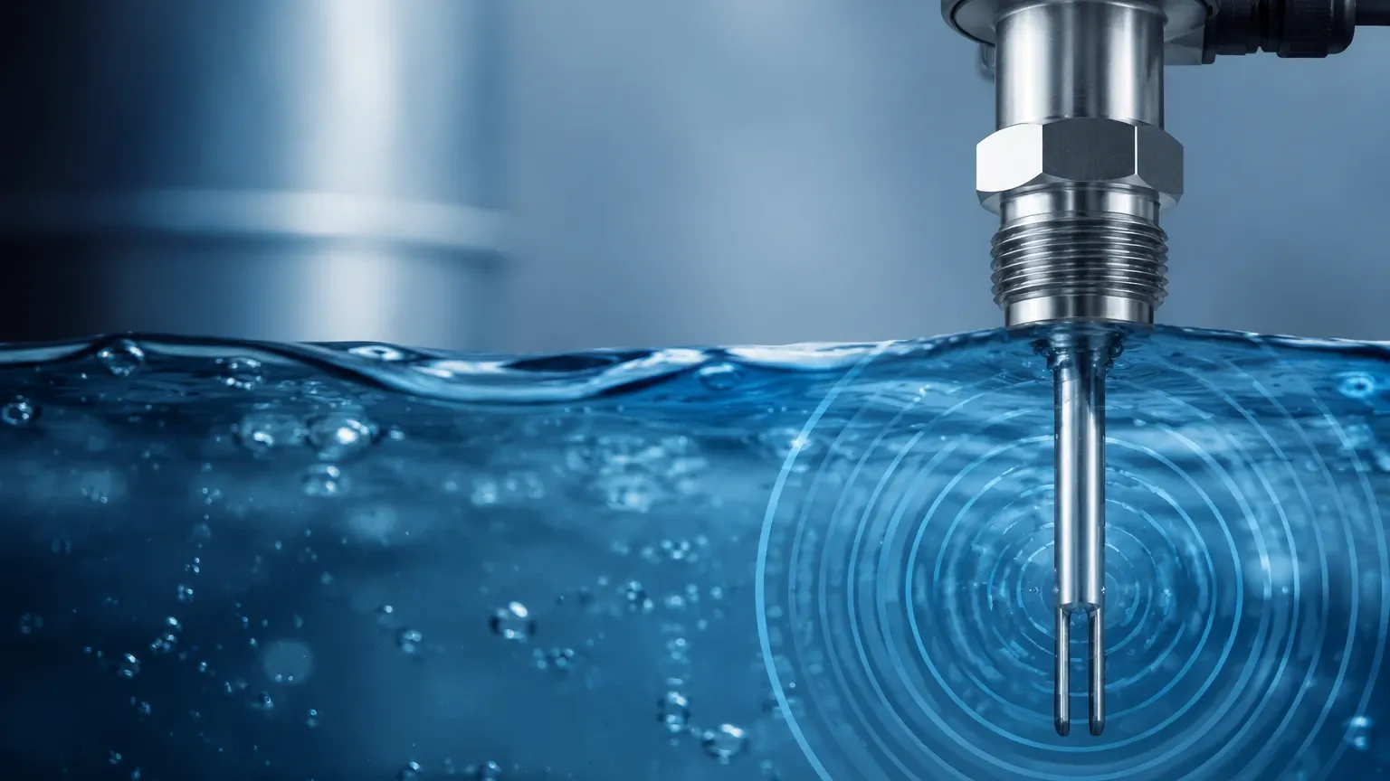
In an industrial tank application, the sensor probe acts as one plate of the capacitor, while the vessel wall (if metallic) serves as the second plate. If the vessel is non-metallic, a ground reference or a second probe is required to complete the circuit. The space between the probe and the wall is occupied by the process medium, which acts as the dielectric.
The Capacitance Formula
The capacitance of the system is governed by the formula:
$$C = \epsilon_0 \cdot \epsilon_r \cdot \frac{A}{d}$$
Where:
* $C$: Capacitance in Farads.
* $\epsilon_0$: Permittivity of free space (a constant).
* $\epsilon_r$: Dielectric constant (relative permittivity) of the material between the plates.
* $A$: Surface area of the plates.
* $d$: Distance between the plates.
In a fixed installation, the surface area ($A$) and the distance ($d$) remain constant. Therefore, the capacitance is directly proportional to the dielectric constant ($\epsilon_r$) of the material surrounding the probe. Air has a dielectric constant of approximately 1.0. Most industrial liquids and solids have significantly higher dielectric constants (e.g., water $\approx$ 80, oil $\approx$ 2.0). When the material rises and covers the probe, the capacitance increases. The electronics within the switch detect this change and trigger an output signal, such as a relay or a transistor switch.
Components and Construction
A level switch capacitance type typically consists of three primary components:
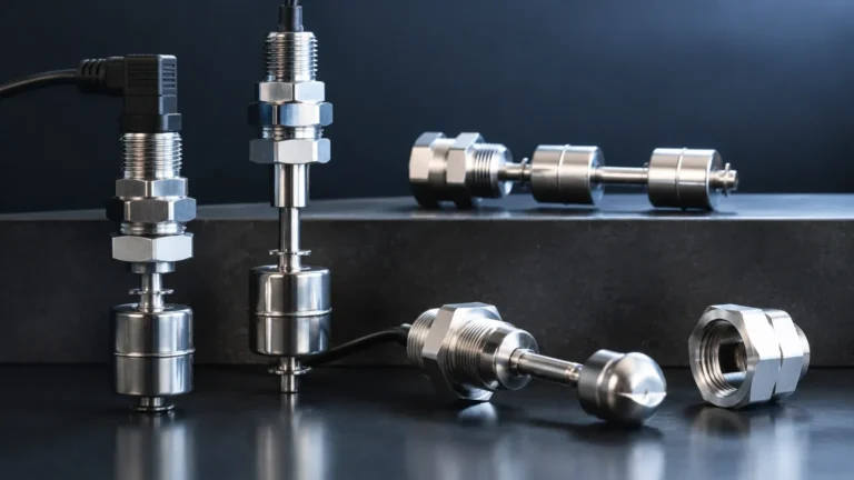
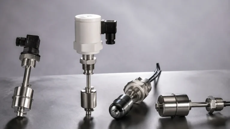
1. The Probe (Sensing Element): This is the part that extends into the vessel. It can be a rigid rod for short distances (typically up to 3 meters or 10 feet) or a flexible cable for deep silos (up to 20 meters or 65 feet). Probes are often coated with insulating materials like PTFE (Teflon) or PFA to prevent short-circuiting when used with conductive liquids.
2. The Process Connection: This is the mechanical interface (threaded or flanged) that secures the switch to the tank. It must be compatible with the tank's pressure and temperature requirements.
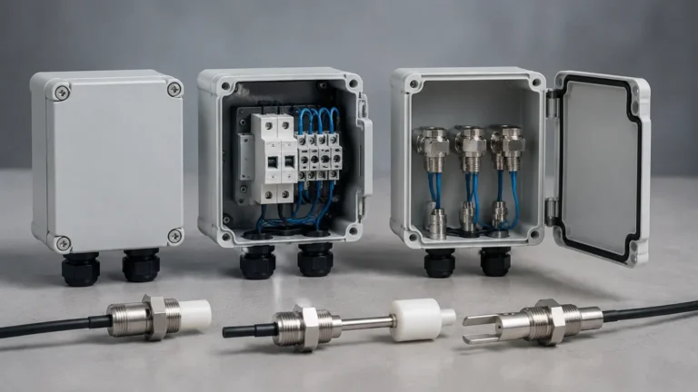
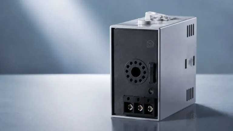
3. The Electronics Enclosure: This housing contains the circuitry that generates the high-frequency signal, measures the capacitance change, and provides the switching output. Modern units often include "RF Admittance" technology, which is an advanced form of capacitance measurement designed to ignore the effects of material buildup on the probe.
Selecting the Right Level Switch Capacitance Type
Choosing the correct configuration depends heavily on the physical and chemical properties of the medium being measured. The following table provides a general selection framework based on common industrial media.
Selection Table: Media vs. Probe Configuration
| Medium Type | Dielectric Constant ($\epsilon_r$) | Recommended Probe Type | Considerations |
| :— | :— | :— | :— |
| Clean Water | ~80 | Fully Insulated (PTFE/PFA) | Conductive; requires insulation to prevent shorting. |
| Oils / Hydrocarbons | 1.8 – 4.0 | Non-Insulated or Insulated | Low $\epsilon_r$ requires high sensitivity electronics. |
| Dry Powders (Grain/Sand) | 1.5 – 3.0 | Rigid Rod or Flexible Cable | High abrasion may require reinforced probes. |
| Slurries / Sticky Liquids | Variable | RF Admittance Type | Buildup on probe can cause false triggers; active shield required. |
| Corrosive Acids | High | Fully PFA/PTFE Encapsulated | Chemical compatibility of the wetted parts is critical. |
| Non-Metallic Tanks | N/A | Dual Probe or Ground Strap | The tank wall cannot act as a ground; a reference is needed. |
Installation and Engineering Considerations
Proper installation is critical to ensure the reliability of a level switch capacitance type. Engineers must account for the geometry of the vessel and the behavior of the material.
1. Mounting Orientation
* Horizontal Mounting: Common for point level detection in small tanks. The probe should be installed with a slight downward angle (approx. 5-10 degrees) to allow liquid to drain off the probe, reducing the risk of false alarms due to residual film.
* Vertical Mounting: Ideal for high-level alarms where the probe must reach down from the top of a vessel. It is also used for low-level detection if the probe is long enough.
2. The "Dead Zone"
There is typically a small region near the process connection where the switch is not sensitive. This is known as the inactive length or dead zone. When calculating the alarm point, engineers must ensure the active part of the probe is positioned exactly where the level detection is required.
3. Grounding and Reference
For the capacitance circuit to work, there must be a clear path to ground. In metal tanks, the tank wall is the ground. In plastic or fiberglass tanks, a "grounding rod" or a dual-probe system must be used. Without a stable reference, the capacitance measurement will drift, leading to inconsistent switching.
4. Proximity to Internal Structures
The probe should be installed away from agitators, baffles, or fill streams. If the probe is too close to a metal structure, the base capacitance may be too high, reducing the sensitivity of the device to the actual process material.
Advantages and Limitations
Advantages
* No Moving Parts: Unlike float switches, there are no mechanical components to jam or wear out, making them suitable for high-vibration environments.
* High Temperature/Pressure: Capacitance switches can be engineered to withstand temperatures exceeding 200°C (392°F) and high pressures (up to 100 bar / 1450 psi).
* Versatility: They work with liquids, granules, and interfaces.
* Adjustable Sensitivity: Most modern units allow the user to calibrate the switch to ignore foam or detect only the liquid phase.
Limitations
* Dielectric Dependency: If the dielectric constant of the material changes significantly (e.g., changing from one chemical to another in a multi-purpose tank), the switch may require recalibration.
* Material Buildup: While RF Admittance versions mitigate this, heavy coating of conductive material can still cause false switching in standard capacitance models.
* Conductivity Sensitivity: If the medium is highly conductive, an uninsulated probe will short out immediately upon contact with the liquid.
Frequently Asked Questions (FAQs)
Q: Can a capacitance level switch detect the interface between oil and water?
A: Yes. Because water has a very high dielectric constant ($\epsilon_r \approx 80$) and oil has a low one ($\epsilon_r \approx 2$), the switch can be calibrated to trigger only when the probe makes contact with the water layer, effectively ignoring the oil.
Q: Does the shape of the tank affect the measurement?
A: In most point-level applications, the shape of the tank does not significantly impact performance as long as there is a consistent distance between the probe and the ground reference (tank wall or ground rod).
Q: What is the difference between standard capacitance and RF Admittance?
A: Standard capacitance measures the total change in charge storage. RF Admittance uses a high-frequency signal and an "active shield" section on the probe to separate the resistance of the buildup from the capacitance of the actual material, significantly improving reliability in sticky applications.
Q: How do I calibrate a level switch capacitance type?
A: Most units feature a "Teach" button or potentiometers. Calibration usually involves setting the "Empty" state (probe in air) and the "Full" state (probe covered by material). Some advanced digital units can be calibrated via HART or Bluetooth without filling the tank.
Conclusion
The level switch capacitance type is a robust and flexible solution for industrial level monitoring. By understanding the dielectric properties of the process media and ensuring proper grounding and probe selection, engineers can implement a maintenance-free level control system. For applications involving complex geometries or extreme environments, it is advisable to consult with a specialist manufacturer to ensure the hardware configuration matches the specific demands of the process.
For more information on specific models and technical specifications, you may Review product options and application support to find the ideal match for your industrial requirements.