Level Switch Drawing
Level Switch Drawing
In industrial process control, the accuracy of a technical level switch drawing is fundamental to the successful integration of point level detection systems. Whether designing a wastewater treatment plant or a chemical storage facility, engineers rely on these drawings to ensure that the selected instruments fit the physical constraints of the vessel, meet electrical requirements, and interface correctly with the control logic.
At Welk, we recognize that a level switch is more than just a component; it is a critical safety and automation tool. Understanding the nuances of a level switch drawing—from dimensional tolerances to wiring schematics—is essential for preventing costly installation errors and ensuring long-term operational reliability.
Principles of Point Level Measurement
Before diving into the specifics of a level switch drawing, it is important to understand the measurement principles that dictate the physical design and electrical output of these devices. Level Switches are designed to detect the presence or absence of a medium at a specific point, providing a discrete signal (on/off) to a PLC or alarm system.
1. Float Level Switches
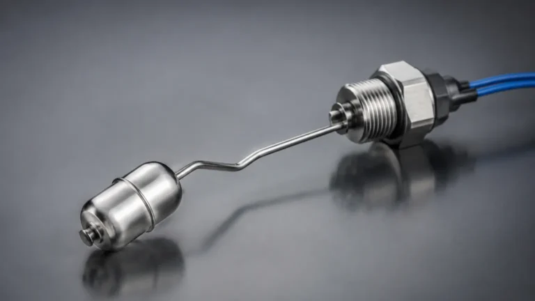
Float switches operate on the principle of buoyancy. A float containing a magnet moves with the liquid level. When the float reaches a predetermined point, the magnetic field actuates a reed switch or a microswitch. The drawing for these units must specify the "swing radius" or the travel distance of the float to avoid interference with tank internals.
2. Vibrating Tuning Fork Switches
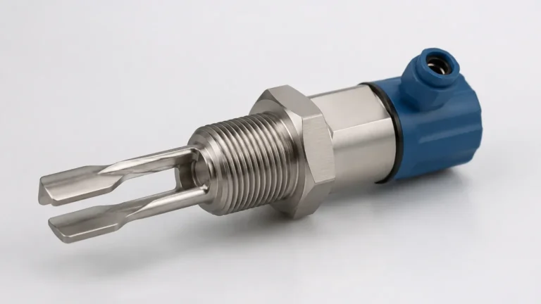
These switches utilize a fork-shaped sensing element that vibrates at its resonant frequency in air. When the fork is immersed in a liquid or solid, the frequency changes. This change is detected by the internal electronics and converted into a switching signal. Drawings for tuning forks focus heavily on the insertion length and the orientation of the tines relative to the flow.
3. Capacitive Level Switches
The probe and the vessel wall (or a reference electrode) form a capacitor. As the medium covers the probe, the dielectric constant changes, altering the capacitance. These are ideal for powders and liquids. The level switch drawing for capacitive models must indicate the "active zone" and any required insulation for conductive media.
4. Hydrostatic and Optic Switches
Hydrostatic switches detect pressure at a specific depth, while optical switches use the refraction of an infrared light beam. Each requires specific mounting orientations that must be clearly detailed in the engineering submittals.
The Role of a Level Switch Drawing in Engineering
A comprehensive level switch drawing serves three primary purposes: mechanical fit-up, electrical integration, and maintenance reference. In a B2B procurement environment, these drawings are usually provided in PDF or DWG formats during the technical clear-out phase of a project.
Dimensional Drawings (Outline Drawings)
Dimensional drawings provide the physical envelope of the instrument. Key data points include:
* Total Length and Insertion Length (L): Usually measured from the bottom of the process connection to the tip of the sensor. For example, a standard tuning fork might have an insertion length of 100 mm (approx. 3.94 inches).
* Process Connection Size: Specification of threads (e.g., 1" NPT, G1/2) or flanges (e.g., DN50 PN16, 2" ANSI 150#).
* Housing Dimensions: The width and height of the electronics enclosure, ensuring there is enough clearance for the cover to be removed during maintenance.
Electrical Schematics (Wiring Diagrams)
The wiring portion of a level switch drawing defines how the device receives power and how it communicates the switch state. Common configurations include:
* SPDT (Single Pole Double Throw): Provides one common, one normally open (NO), and one normally closed (NC) contact.
* DPDT (Double Pole Double Throw): Two sets of SPDT contacts for redundant signaling or controlling two separate circuits.
* Transistor Output (PNP/NPN): Common in DC-powered automation for high-speed switching.
* Two-Wire AC/DC: Often used for simple series-loop alarms.
Installation Layouts
These drawings illustrate the recommended mounting position (top-mounted, side-mounted, or angled) and the minimum distance required from tank walls or agitator blades to prevent false triggering.
Technical Selection Criteria
Choosing the right instrument involves matching the application's physical and chemical properties to the specifications found in the level switch drawing. The following table provides a general comparison of common technologies used in industrial automation.
| Technology | Typical Media | Max Temperature | Max Pressure | Key Drawing Consideration |
| :— | :— | :— | :— | :— |
| Float Switch | Clean Liquids | 150°C (302°F) | 40 bar | Float travel clearance |
| Tuning Fork | Liquids/Solids | 230°C (446°F) | 64 bar | Tine orientation to flow |
| Capacitive | Acids/Powders | 200°C (392°F) | 25 bar | Probe insulation type |
| Conductive | Conductive Liquids | 100°C (212°F) | 10 bar | Electrode spacing |
Installation Considerations and Best Practices
When reviewing a level switch drawing for installation, engineers must account for environmental and process factors that could affect performance.
1. Avoid Turbulence: If the switch is installed near an inlet pipe, the drawing should specify a stilling well or a baffle. Turbulence can cause a float switch to bounce or a tuning fork to experience mechanical fatigue.
2. Nozzle Length: For side-mounted switches, the nozzle length must be shorter than the insertion length. If the nozzle is too long, material (especially viscous liquids or solids) can build up inside the nozzle, preventing the switch from resetting when the level drops.
3. Orientation: For vibrating forks, the tines should be oriented so that the liquid can drain off easily. In horizontal installations, the tines should be vertical (side-by-side) rather than horizontal (one above the other) to prevent material entrapment.
4. Cable Entry: The level switch drawing will show the position of the cable glands. Always install the device so that the cable entries point downward to prevent moisture from entering the housing via the conduit (creating a "drip loop").

Limitations and Common Risks
Despite their apparent simplicity, misinterpreting a level switch drawing can lead to significant project delays.
* Material Incompatibility: A drawing might specify 316 Stainless Steel, but if the process medium is highly corrosive (like hydrochloric acid), the sensor may fail within weeks. Always cross-reference the wetted parts list in the drawing with a chemical compatibility chart.
* Dead Zones: Every switch has a small region where it cannot detect level accurately. For float switches, this is the area at the very top and bottom of the stem where the float cannot travel.
* Coating and Build-up: In applications involving slurries or sticky resins, material build-up on the sensor can cause "bridging." While some capacitive switches have active shield technology to ignore build-up, this must be confirmed in the technical specifications.
* Voltage Mismatch: Connecting a 24V DC transistor output switch to a 230V AC circuit will result in immediate hardware failure. Always verify the power supply requirements on the electrical schematic of the drawing.
Frequently Asked Questions (FAQs)
Q: Can I shorten the probe length of a level switch in the field?
A: Generally, no. Most level switches, especially tuning forks and capacitive probes, are factory-calibrated to a specific length. Cutting the probe will change its frequency or capacitance and void the warranty. Only specifically designed "cut-to-length" rod or cable probes can be modified.
Q: What is the difference between "Fail-Safe High" and "Fail-Safe Low" in a drawing?
A: This refers to the relay state in the event of a power failure. Fail-safe high (FSH) means the relay de-energizes when the level is high or power is lost, preventing an overfill. Fail-safe low (FSL) means the relay de-energizes when the level is low or power is lost, preventing a pump from running dry.
Q: Why does the drawing show a 3-wire and a 4-wire version of the same switch?
A: A 3-wire switch typically uses the same power source for the electronics and the output signal. A 4-wire switch usually provides a "dry contact" (volt-free), allowing the user to switch a different voltage than the one powering the instrument.
Final Project Confirmation Steps
Before finalizing an order based on a level switch drawing, project managers should confirm the following:
1. Tagging Requirements: Ensure the instrument tag number (e.g., LSH-101) is included in the drawing and will be engraved on the physical nameplate.
2. Certification Marks: Verify that the drawing indicates necessary certifications such as ATEX/IECEx for hazardous areas or SIL 2 for functional safety.
3. Connection Compatibility: Double-check that the flange or thread standard on the drawing matches the mating connection on the tank.
By meticulously reviewing the level switch drawing and aligning it with the specific demands of the industrial environment, engineers can ensure a seamless transition from design to operation. Welk provides detailed technical documentation and customized OEM/ODM services to ensure our level measurement solutions meet the exact requirements of your global projects.