Level Switch Dwyer
Level Switch Dwyer
In the landscape of industrial process control, the ability to accurately detect the presence or absence of a substance at a specific point is fundamental to safety and efficiency. Level switches serve as the primary line of defense against tank overfills, pump dry-running, and inventory depletion. Among the established names in the instrumentation sector, the level switch Dwyer range is frequently specified by engineers for its mechanical simplicity and reliability. This guide examines the underlying principles of level switching, the specific technologies employed by Dwyer, and the critical factors involved in selecting the right instrument for industrial applications.
Understanding the Principles of Level Switching
Before selecting a specific model, it is essential to understand the physics behind level detection. Unlike continuous level transmitters that provide a constant signal (e.g., 4-20mA), a level switch provides a discrete output—typically a dry contact or a transistor switch—when a pre-defined threshold is reached.
Mechanical Buoyancy (Float Switches)
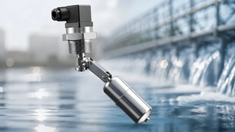
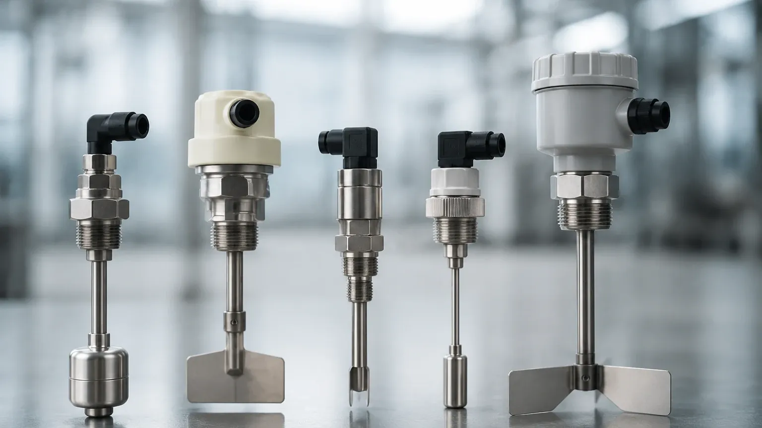
Float-operated switches utilize the principle of buoyancy. A float, designed with a density lower than the process liquid, rises or falls with the fluid level. Most industrial float switches, including many within the Dwyer portfolio, use magnetic coupling. As the float moves, an internal magnet actuates a reed switch or a microswitch located outside the process boundary. This design ensures that the electrical components remain isolated from the media.
Vane/Paddle Principle
For bulk solids and powders, mechanical paddle switches are the standard. A small motor rotates a paddle at a low speed. When the material reaches the paddle, the resulting torque overcomes a spring-loaded mechanism, stopping the motor and tripping the switch. This technology is robust and unaffected by the dielectric properties of the material.
Capacitance and Conductivity
Electronic level switches rely on the electrical properties of the media. Capacitive switches measure the change in capacitance between a probe and the tank wall. Conductive switches, used only with conductive liquids like water, complete an electrical circuit when the liquid bridges the gap between two electrodes.
Ultrasonic and Optical
Non-contact switches use sound waves or light beams. Ultrasonic switches emit a pulse and measure the time of flight or the attenuation of the signal to determine if a liquid is present at the sensor face. These are ideal for corrosive or high-purity applications where contact is undesirable.
Overview of Dwyer Level Switch Technologies
Dwyer Instruments offers a diverse range of switches tailored for different environmental conditions. Their designs often focus on ruggedness and ease of field maintenance.
The Flotect® Series (L4 and L6)
The Flotect series is perhaps the most recognized line of level switch Dwyer produces. These are vane-operated or float-operated switches designed for high-pressure and hazardous environments.
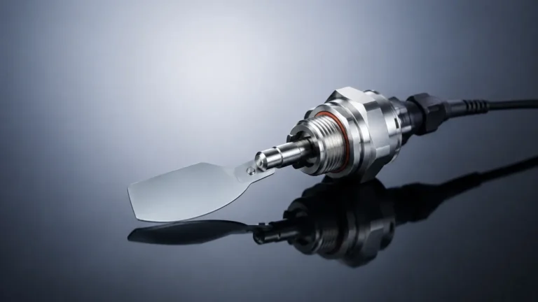
* Model L4: Primarily used for flow detection but adaptable for level, the L4 uses a vane that is pushed by the media. It features a leak-proof design because the switch body is separated from the process by a solid metal wall, with movement transferred magnetically.
* Model L6: A compact float switch designed for liquid level control. It is often used in oil refineries, chemical plants, and water treatment facilities. The L6 is available in various materials, including brass and 316 stainless steel, to handle pressures up to 138 bar (2000 psi).
Vertical and Horizontal Float Switches
For simpler tank applications, the F6 and F7 series provide versatile mounting options.
* Vertical Mount (F7): These are installed through the top or bottom of a tank. They can feature multiple switch points on a single stem, allowing for "High," "Low," and "Low-Low" alarms in one unit.
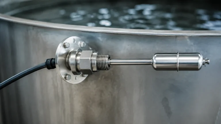
* Horizontal Mount (F6): These are installed through the side wall of a vessel. When the liquid level reaches the horizontal float, it hinges upward, actuating the internal switch.
Paddle Level Switches (Series PLS)
For silos and hoppers containing grain, plastic pellets, or cement, the PLS series is the standard. These units are designed with a triple-shaft seal to prevent dust from entering the motor housing, ensuring longevity in harsh dry-bulk environments.
Selection Criteria for Industrial Level Switches
Choosing the correct Level Switches requires a detailed analysis of the process conditions. Engineers must look beyond the brand name and focus on technical specifications.
| Feature | Consideration | Impact on Selection |
| :— | :— | :— |
| Media Type | Liquid, Slurry, or Solid | Determines if a float, paddle, or capacitive probe is needed. |
| Operating Pressure | Vacuum to High Pressure | Mechanical switches must have housings rated for the maximum vessel pressure (e.g., PN16, PN40). |
| Temperature Range | -40°C to +200°C+ | High temperatures may require remote-mounted electronics or specialized gaskets. |
| Chemical Compatibility | Corrosive vs. Neutral | Wetted parts must be compatible (316SS, Hastelloy, PVC, or PTFE). |
| Hazardous Area Rating | ATEX, IECEx, or UL | Determines if the switch requires an explosion-proof housing or intrinsically safe wiring. |
| Mounting Orientation | Top, Bottom, or Side | Influences the physical form factor and the length of the probe or float stem. |
Installation Best Practices and Maintenance
Proper installation is critical to prevent false triggering and mechanical failure. Even a high-quality level switch Dwyer provides can fail if environmental factors are ignored.
1. Avoid Turbulence: Float switches should not be installed directly near an inlet pipe where turbulent flow can cause the float to bounce. If turbulence is unavoidable, a "still pipe" or "stilling well" (a perforated pipe surrounding the float) should be used to stabilize the liquid level around the sensor.
2. Orientation and Clearance: For horizontal switches, ensure there is enough internal clearance for the float to move through its full arc. For vertical switches, ensure the stem is perfectly plumb to prevent the float from sticking due to friction.
3. Wiring and Sealing: Use a drip loop in the conduit to prevent moisture from traveling down the wires into the switch housing. Ensure the NEMA or IP-rated covers are tightened correctly after calibration.
4. Bulk Solids Considerations: When installing paddle switches in silos, the unit should be positioned out of the direct path of the material flow during filling to prevent mechanical damage to the paddle.
Limitations and Common Risks in Level Detection
While level switches are generally reliable, they are not "set and forget" devices. Understanding their limitations is key to system design.
* Coating and Buildup: In applications involving wastewater or viscous chemicals, material can build up on floats or probes. This "bridging" can cause a switch to stay in the "on" position even after the level has dropped. Capacitive switches with "active shield" technology or vibrating fork switches are often preferred in these scenarios.
* Specific Gravity Changes: Float switches are calibrated for a specific fluid density. If the process fluid changes (e.g., switching from water to a light oil), the float may no longer have sufficient buoyancy to actuate the switch.
* Mechanical Wear: Because paddle switches and float switches have moving parts, they are subject to mechanical fatigue over millions of cycles. In high-cycle applications, solid-state electronic switches (like ultrasonic or optical) may offer a longer service life.
Why Professional Selection Matters
Manufacturers like Welk provide a broad spectrum of level measurement solutions that complement or serve as alternatives to the Dwyer line. While Dwyer is well-regarded for general-purpose industrial switching, complex applications involving extreme pressures, highly corrosive media, or the need for integrated digital communication (such as HART or Modbus) may require a more customized approach.
Welk’s expertise in both mechanical and electronic level detection ensures that the chosen instrument aligns with the specific safety integrity level (SIL) requirements of the plant. Whether it is a magnetic level gauge for visual confirmation or a redundant radar level system for high-value inventory, the goal is always to match the technology to the risk profile of the application.
Frequently Asked Questions (FAQs)
Q: Can a level switch be used for continuous level measurement?
No. A level switch only detects if the material has reached a specific point. For continuous tracking (e.g., 0% to 100% full), a level transmitter (radar, ultrasonic, or hydrostatic) is required.
Q: What is the difference between a N.O. and N.C. contact?
Normally Open (N.O.) means the circuit is open when the switch is in its "resting" state (e.g., tank empty). Normally Closed (N.C.) means the circuit is complete in the resting state. Most Dwyer switches allow the user to choose or wire for either configuration.
Q: How do I handle foam in a liquid level application?
Foam can trick ultrasonic and some capacitive switches. Mechanical float switches are generally unaffected by foam, as the float will sink through the foam and respond to the actual liquid surface.
Q: Is it possible to test a level switch without filling the tank?
Yes, many industrial switches include a manual test lever or a magnetic test point that allows technicians to simulate the movement of the float or vane to verify that the electrical circuit and downstream alarms are functioning correctly.
By carefully evaluating the physical properties of the media and the mechanical requirements of the vessel, engineers can deploy level switch Dwyer units or Welk alternatives to create a robust and reliable level control system. For further technical specifications and product comparisons, reviewing the full range of Level Switches is recommended for any new installation or system retrofit.