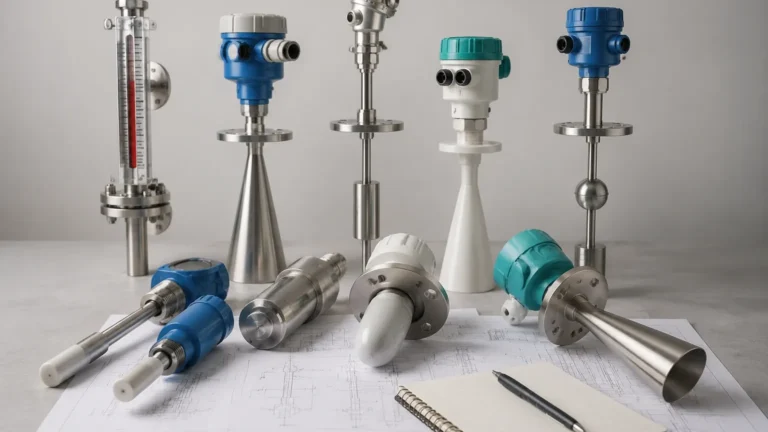
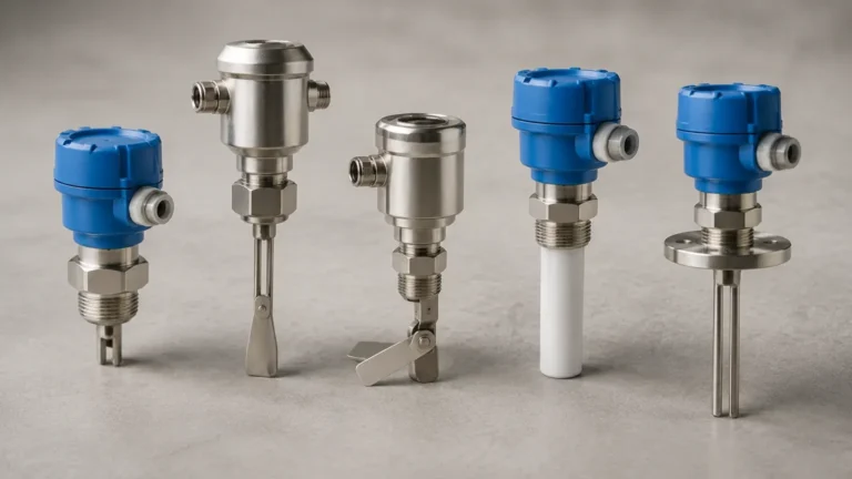
Level Switch Gauge
Level Switch Gauge
In the landscape of industrial process control, the ability to both visualize and automate fluid levels is a critical safety and operational requirement. A level switch gauge represents an integrated solution that combines the visual monitoring capabilities of a level gauge with the discrete control functions of Level Switches. This dual-functionality ensures that operators have a real-time visual reference on the plant floor while the control system receives reliable signals for pump automation, high-level alarms, or emergency shutdowns.
For engineers and facility managers, understanding the synergy between these two technologies is essential for optimizing tank monitoring. Whether applied in water treatment, chemical processing, or oil and gas storage, the level switch gauge serves as a primary interface between physical liquid states and electronic control logic.
Understanding the Measurement Principles
To effectively implement a level switch gauge, one must first understand the underlying principles of the gauge and the switch components. In most B2B industrial applications, this combination is typically achieved using a Magnetic Level Gauge (MLG) as the foundation.
The Magnetic Level Gauge Principle
A magnetic level gauge consists of a bypass chamber (a vertical pipe) connected to the side of a vessel via flanges or threaded connections. Inside this chamber is a float containing a high-intensity permanent magnet. Because the liquid level in the chamber matches the level in the tank (based on the principle of communicating vessels), the float rises and falls with the fluid.
On the exterior of the chamber, a visual indicator—often a series of bicolour magnetic flaps or a follower—interacts with the float's magnetic field. As the float moves, the flaps flip to change color (e.g., from white to red), providing a clear visual representation of the level without the risks associated with glass sight tubes.
The Integration of Level Switches
The "switch" aspect of a level switch gauge is realized by mounting external sensing elements onto the bypass chamber. These switches are typically bistable reed switches or proximity sensors encased in protective housings.
When the float inside the chamber reaches the height of a specific switch, the magnetic field of the float actuates the switch contacts. This changes the electrical state (from Open to Closed, or vice versa), sending a signal to a PLC (Programmable Logic Controller) or a local alarm. Because these switches are clamped to the outside of the chamber, they do not come into contact with the process media, which significantly enhances their lifespan and simplifies maintenance.
Key Evaluation Criteria for a Level Switch Gauge
Selecting the right level switch gauge requires a thorough analysis of the process environment. A mismatch between the instrument specifications and the liquid properties can lead to float failure or inaccurate switching.
1. Specific Gravity (Density)
The float is the heart of the system. It must be engineered to float in the specific liquid being measured. If the liquid’s specific gravity (SG) is lower than the float's design, the float will sink, rendering both the gauge and the switches useless. Conversely, if the SG is significantly higher, the float may sit too high in the liquid, causing a calibration offset. Standard floats are often designed for an SG of 0.8 to 1.2, but custom floats can be manufactured for lighter hydrocarbons or heavy brines.
2. Pressure and Temperature Ratings
Industrial tanks often operate under high pressure or extreme temperatures. The bypass chamber and the float must be rated for the maximum design pressure of the vessel. For high-temperature applications (exceeding 200°C), specialized insulation and high-temperature switches are required to prevent the magnetic field from degrading (the Curie point) and to protect the electrical components.
3. Material Compatibility
The wetted parts—the chamber and the float—must be chemically compatible with the media. Common materials include:
* 304/316 Stainless Steel: Standard for water and most oils.
* PTFE/PFA Lining: Used for highly corrosive acids.
* PP/PVDF: Suitable for low-pressure chemical storage.
Practical Selection Table
The following table provides a comparison of common switch types used in conjunction with level gauges to help determine the best fit for your application.
| Switch Type | Sensing Method | Best Use Case | Temperature Range | Limitation |
| :— | :— | :— | :— | :— |
| Magnetic Reed Switch | Float Magnetism | Standard alarm/control | -40°C to +250°C | Sensitive to heavy vibration |
| Bistable Switch | Magnetic Latching | Maintaining state after float passes | -50°C to +350°C | Higher cost than standard reed |
| Tuning Fork Switch | Vibration Damping | High-viscosity liquids | -50°C to +150°C | Requires process penetration |
| Non-Contact Ultrasonic | Sound Reflection | Redundant verification | -20°C to +90°C | Limited by foam or vapor |
Installation Considerations and Best Practices
Proper installation is paramount for the reliability of a level switch gauge. Even the most advanced instrument will fail if the physical setup is flawed.
Vertical Alignment
The bypass chamber must be installed perfectly vertical. Most manufacturers recommend a maximum deviation of less than 3 degrees. If the chamber is tilted, the float may experience friction against the chamber walls, leading to "sticking" or erratic visual and switch performance.
Magnetic Interference
Since the system relies on magnetic fields, it must be kept away from large ferrous structures or high-voltage cables that could generate electromagnetic interference. If the tank itself is made of carbon steel, ensure the gauge is mounted with sufficient standoff distance to prevent the float magnet from being attracted to the tank wall.
Venting and Draining
Every level switch gauge should be equipped with a vent valve at the top and a drain valve at the bottom. This allows for safe commissioning and maintenance. Periodically flushing the chamber through the drain valve prevents the buildup of sediment or scale that could trap the float.
Wiring and Signal Integrity
When connecting the switches to the control room, use shielded cables to prevent signal noise. For hazardous areas, ensure the switches are ATEX or IECEx certified and use intrinsic safety barriers where required.
Common Risks and Limitations
While highly versatile, the level switch gauge is not a universal solution for every process. Engineers should be aware of the following risks:
* Fouling and Coating: In liquids that crystallize or contain heavy solids, the float can become coated. This increases the float's weight and may eventually cause it to seize within the chamber.
* High Viscosity: Extremely viscous liquids (above 500 cP) can slow the movement of the float, leading to a significant delay between the actual level change and the switch activation.
* Flash Evaporation: If the liquid in the chamber boils or flashes into vapor rapidly, the resulting turbulence can damage the float or cause it to bounce, triggering false alarms.
* Magnetic Particles: If the process fluid contains iron filings or magnetic scale, these particles will adhere to the float's magnet, eventually causing it to bridge the gap between the float and the chamber wall, resulting in a mechanical jam.
Frequently Asked Questions (FAQ)
Q: Can I add more switches to my level switch gauge after it has been installed?
A: Yes, one of the primary advantages of a magnetic level switch gauge is that the switches are externally mounted. You can typically add or reposition switches by simply clamping them to the outside of the chamber and adjusting their height to the desired setpoint.
Q: How do I test the switches without draining the tank?
A: Most magnetic level gauges allow for a "test magnet" to be used. By sliding an external magnet along the outside of the chamber, you can simulate the float's movement to flip the visual flags and trigger the switches for testing purposes.
Q: What is the difference between a level switch gauge and a level transmitter?
A: A level switch gauge provides visual indication and point-level signals (On/Off). A level transmitter provides a continuous signal (e.g., 4-20mA or Modbus) representing the exact percentage of the tank's volume. Many level switch gauges can be fitted with a reed-chain transmitter to provide all three functions: visual, point-level, and continuous monitoring.
Q: Does the size of the chamber matter?
A: Yes. The chamber diameter must be slightly larger than the float to allow for a liquid buffer, but not so large that the magnetic field fails to reach the external switches or indicator. Standard chamber sizes are typically 2" or 2.5" (50mm to 65mm).
Conclusion
The level switch gauge remains a cornerstone of industrial instrumentation because it addresses the fundamental need for both human-readable data and machine-actionable signals. By selecting a system that accounts for specific gravity, chemical compatibility, and environmental stressors, facilities can achieve a high degree of operational safety.
When planning your next tank monitoring project, confirm the specific gravity of your media and the required alarm setpoints. For specialized configurations or high-pressure requirements, consulting with a manufacturer like Welk ensures that the equipment is tailored to your specific process boundaries. For a comprehensive range of point-control solutions, you can explore various Level Switches designed to integrate seamlessly with modern gauge technology.