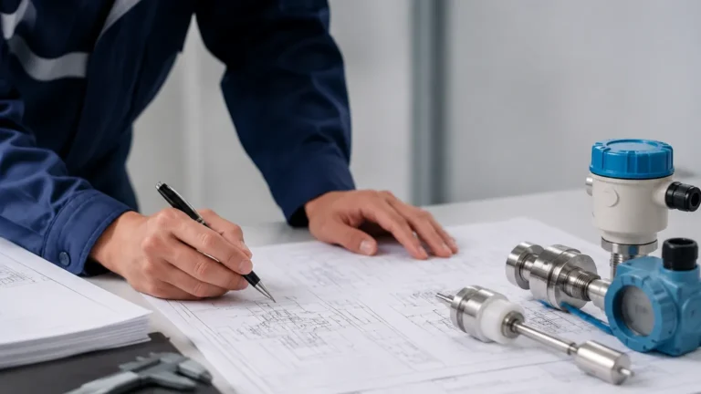
Level Switch Keyence
Level Switch Keyence
In the landscape of industrial automation, point-level detection serves as a fundamental safeguard for process continuity and equipment protection. Among the leading providers of high-precision sensing technology, Keyence has established a significant presence with its range of level switches designed for demanding factory environments. This guide examines the technical principles, application criteria, and engineering considerations surrounding the level switch Keyence portfolio, while providing a broader context for selecting the right Level Switches for industrial liquid and solid management.
Understanding Level Measurement Principles
Before selecting a specific sensor model, it is essential to understand the physical principles that govern level detection. Level switches generally operate by detecting a change in a physical property when the medium (liquid or solid) comes into contact with the sensor probe or enters its detection field.
1. Guided Wave Radar (TDR)
Guided Wave Radar (GWR) utilizes Time Domain Reflectometry. The sensor emits a low-energy microwave pulse along a probe (waveguide). When the pulse hits the surface of the medium, a portion of the energy is reflected back to the transmitter due to the change in the dielectric constant (εr). By measuring the time-of-flight, the sensor determines the exact level. This method is highly resistant to steam, foam, and pressure changes.
2. Capacitive Sensing
Capacitive level switches treat the sensor probe and the tank wall (or a second probe) as two plates of a capacitor. As the medium rises, it displaces air, changing the dielectric constant between the plates and increasing the measured capacitance. This change triggers the switch output. Capacitive sensors are effective for both liquids and solids but may require calibration for different materials.
3. Ultrasonic Detection
Ultrasonic sensors emit high-frequency sound waves that bounce off the surface of the medium. The time taken for the echo to return is converted into a distance measurement. While often used for continuous measurement, they are frequently employed as non-contact level switches. Their performance can be affected by heavy foam or significant air turbulence.
4. Optical Refraction
Optical level switches use an infrared LED and a prism. In the absence of liquid, the light reflects internally within the prism back to a receiver. When liquid covers the prism, the light is refracted into the medium, and the receiver detects a loss of signal, triggering the switch. These are ideal for clean liquids and compact spaces.
The Level Switch Keyence Portfolio: Technical Overview
Keyence level switches, particularly the FL and N series, are engineered to address the specific challenges of the food, pharmaceutical, and automotive industries. Their design philosophy often focuses on "mounting-independent" performance, reducing the need for complex calibration.
The FL Series (Guided Wave Radar)
The FL series is Keyence’s flagship solution for liquid level detection. Unlike traditional float switches that are prone to mechanical failure due to buildup, the FL series uses GWR technology. It is designed to ignore the effects of coating or scale on the probe, which is a common pain point in chemical processing and wastewater treatment.
The N Series (Capacitive/Pulse)
The N series often utilizes specialized pulse-based detection to differentiate between the actual liquid level and residue or foam. This makes them particularly useful in small-diameter pipes or tanks where traditional sensors might struggle with "bridging" or false triggers caused by droplets on the sensor face.
Selection Criteria for Industrial Level Switches
Choosing between a level switch Keyence model and other industrial alternatives requires a detailed analysis of the process environment. The following table outlines key selection factors:
| Factor | Guided Wave Radar (FL Series) | Capacitive (N Series) | Ultrasonic | Optical |
| :— | :— | :— | :— | :— |
| Medium Type | Liquids (Oil/Water/Chemicals) | Liquids and Solids | Liquids and Granules | Clean Liquids |
| Viscosity | High (Resistant to coating) | Moderate | N/A (Non-contact) | Low |
| Foam Resistance | Excellent | Moderate | Poor | Good |
| Dielectric Constant | Low to High | Must be > 1.5 | N/A | N/A |
| Pressure Range | Up to 4 MPa (40 bar) | Atmospheric to Moderate | Atmospheric | Atmospheric |
| Installation Space| Requires probe length | Compact | Requires top clearance | Extremely Compact |
Engineering and Installation Considerations
Proper installation is critical to ensure the reliability of a level switch. Even high-end sensors like those from Keyence can fail if environmental factors are ignored.
1. The "Dead Zone" (Blocking Distance)
Every level sensor has a "dead zone" near the mounting flange where measurement is either impossible or inaccurate. For ultrasonic sensors, this is typically 50 mm to 200 mm (2" to 8"), depending on the frequency. For GWR sensors, the upper dead zone is usually smaller but must still be accounted for in tank design to prevent overfilling.
2. Turbulence and Agitators
In tanks with active mixing, the surface of the liquid is rarely stable. While GWR sensors are more stable than ultrasonic ones in these conditions, it is often necessary to install a "stillpipe" or "bypass chamber." This provides a calm area for the sensor to measure, preventing rapid switching (chattering) of the output signal.
3. Material Compatibility
The wetted parts of the level switch must be chemically compatible with the medium. Common materials include:
* 316L Stainless Steel: Standard for food, beverage, and general industrial use.
* PTFE/PFA Coating: Required for highly corrosive acids or bases.
* PEEK: Often used in sanitary applications for its high-temperature resistance and durability.
4. Output Integration
Modern level switches often provide multiple output options. Beyond the standard PNP/NPN transistor outputs, many Keyence models support IO-Link. This digital protocol allows for remote parameter setting, real-time monitoring of the sensor's health, and easier integration into Industry 4.0 PLC architectures.
Limitations and Common Risks
While the level switch Keyence range is robust, certain limitations apply to all point-level technologies:
* Dielectric Sensitivity: For GWR and capacitive switches, if the dielectric constant of the liquid is too low (e.g., certain pure hydrocarbons), the signal reflection may be too weak to detect. In such cases, specialized low-dielectric probes are required.
* Heavy Buildup: Although many sensors claim to be "buildup resistant," extreme crystallization or thick sludge can eventually bridge the gap between the probe and the tank wall, leading to a permanent "high" signal.
* Ambient Noise: Ultrasonic sensors can be sensitive to acoustic noise from pneumatic filling systems or high-pressure steam leaks.
Practical Maintenance Guidance
To maintain the accuracy of level switches over a long service life, a routine maintenance schedule should be implemented:
1. Visual Inspection: Check for physical damage to the probe or cable entry points. Ensure that the cable glands are tight to prevent moisture ingress (IP67/IP69K compliance).
2. Cleaning: In applications involving sticky or viscous fluids, periodic cleaning of the sensor face or probe is necessary. Use cleaning agents that do not degrade the sensor's wetted materials.
3. Verification: Perform a "bump test" by manually raising the level or removing the sensor to verify that the output state changes as expected in the PLC.
Why Diverse Solutions Matter
While Keyence offers high-performance sensors for automation, many industrial applications—particularly in water treatment, oil and gas, and heavy chemical processing—require a broader range of specialized instruments. Manufacturers like Welk provide a comprehensive suite of level measurement tools, including radar level meters, hydrostatic transmitters, and magnetic level gauges. These solutions often complement point-level switches by providing continuous data or mechanical redundancy.
For projects requiring customized OEM/ODM services or specialized materials for extreme environments, exploring a wide range of Level Switches ensures that the selected technology aligns perfectly with the specific pressure, temperature, and chemical requirements of the application.
Frequently Asked Questions (FAQ)
Q: Can a level switch Keyence be used for dry bulk solids?
A: Yes, certain models in the N series and specialized capacitive sensors are designed for solids. However, for heavy grain or large aggregates, a vibrating fork or rotary paddle switch may be more durable.
Q: What is the benefit of IO-Link in a level switch?
A: IO-Link allows the sensor to transmit more than just a binary "on/off" signal. It can provide internal temperature data, signal strength (to predict buildup), and allow for remote configuration without accessing the sensor physically.
Q: How do I handle foam in a tank?
A: If the foam is light and airy, Guided Wave Radar (like the FL series) will typically see through it to the liquid surface. If the foam is dense and wet, it may be detected as the liquid level. In these cases, a hydrostatic pressure transmitter might be a better choice for detecting the true "liquid head."
Q: What is the maximum temperature these switches can handle?
A: Standard industrial level switches usually operate up to 80°C (176°F). High-temperature versions with integrated cooling fins or remote electronics can handle process temperatures exceeding 150°C (302°F).
By understanding the physics of measurement and the specific capabilities of high-end sensors like the level switch Keyence, engineers can design more resilient and efficient automation systems. Whether the goal is to prevent tank overfills or ensure pump protection, selecting the correct technology is the first step toward operational excellence.