Level Switch Namur
Level Switch Namur
In the landscape of industrial automation, particularly within hazardous environments and high-reliability process industries, the integration of standardized communication protocols is essential for safety and interoperability. The level switch namur represents a specialized category of point-level detection devices designed to meet the rigorous requirements of the NAMUR standard, specifically IEC 60947-5-6. As a professional manufacturer, Welk provides these high-precision instruments to ensure that chemical, oil and gas, and water treatment facilities can maintain safe operating levels with advanced diagnostic capabilities.
Selecting a level switch with a NAMUR interface is often a requirement for systems involving intrinsic safety (IS) and functional safety (SIL). This guide explores the technical principles, selection criteria, and installation requirements for these critical industrial components.
Understanding the NAMUR Standard in Level Measurement
NAMUR is an acronym for the *Normenarbeitsgemeinschaft für Mess- und Regeltechnik in der Chemischen Industrie* (User Association of Automation Technology in Process Industries). While the association covers many aspects of industrial standards, in the context of Level Switches, "NAMUR" almost always refers to the electrical interface defined by the IEC 60947-5-6 standard.
This standard defines a two-wire proximity sensor interface that operates on a variable current signal rather than a simple open or closed contact. Unlike a standard transistor (NPN/PNP) or relay output, a NAMUR sensor changes its internal resistance based on the presence or absence of the target medium. This change in resistance results in a change in current consumption, which is then interpreted by a switching amplifier or a safety PLC.
The 2-Wire Current Loop Mechanism
A level switch namur operates on a constant voltage supply, typically around 8.2 V DC provided by an isolated barrier or switching amplifier. The sensor's state is determined by the following current thresholds:
* Logic 0 (Target not detected/Low State): Current is typically between 0.4 mA and 1.2 mA.
* Logic 1 (Target detected/High State): Current is typically between 2.1 mA and 5.0 mA.
By monitoring these specific current levels, the system can distinguish between a valid switching state and a fault condition.
Operating Principles of a Level Switch with NAMUR Output
Before selecting a specific model, it is vital to understand how the physical measurement is converted into the NAMUR signal. While various technologies can be equipped with this interface, the most common are vibrating fork and capacitive sensors.
Vibrating Level Switches
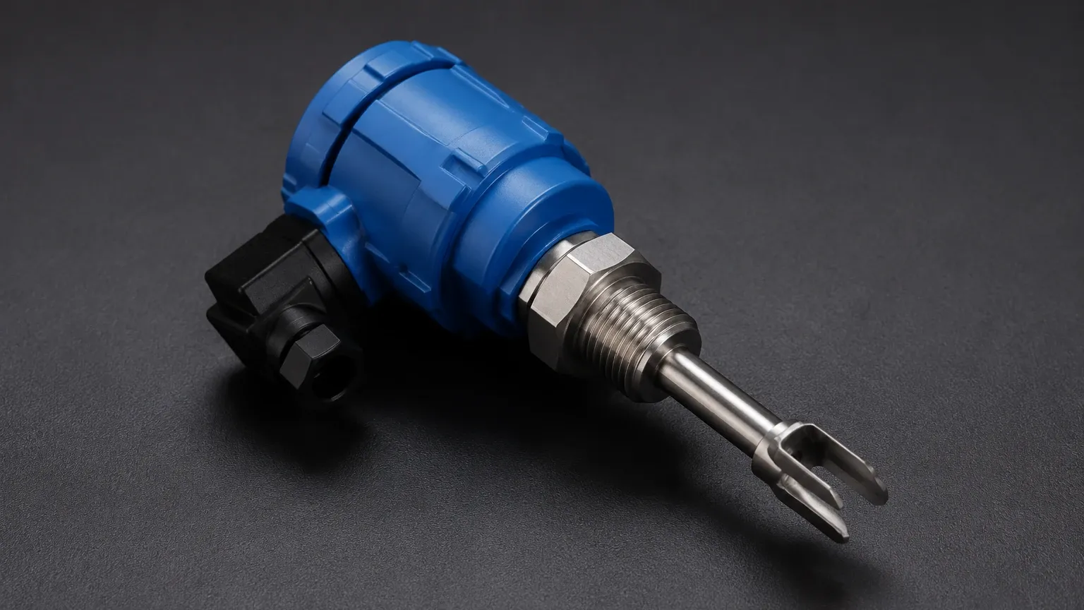
Vibrating fork level switches utilize a piezoelectric crystal to energize a tuning fork at its natural resonance frequency. When the fork is in air, it vibrates freely. When it is submerged in a liquid or solid, the frequency shifts or the amplitude is dampened. The internal electronics of the level switch namur detect this change and adjust the output current to the appropriate NAMUR level. This technology is highly favored for its immunity to bubbles, turbulence, and changing fluid properties like density or conductivity.
Capacitive Level Switches
Capacitive sensors measure the change in electrical capacitance between the probe and the tank wall (or a reference electrode). As the medium rises and covers the probe, the dielectric constant changes, altering the capacitance. For NAMUR variants, the electronics translate this capacitance change into the standardized current signal. These are often used for detecting powders, granulates, or liquids in non-metallic tanks.
Diagnostic Capabilities and Fault Detection
One of the primary reasons engineers specify a level switch namur is for its inherent diagnostic features. Because the signal is a continuous current loop, the control system can detect line faults that a simple dry contact cannot:
1. Wire Breakage: If the current drops below 0.1 mA, the system identifies a broken cable.
2. Short Circuit: If the current rises above 6.0 mA, the system identifies a short circuit in the wiring.
This level of monitoring is essential for Safety Integrity Level (SIL) rated loops, where the failure of a sensor must be detected immediately to prevent an unsafe condition, such as a tank overfill.
Selection Criteria for Level Switch Namur Applications
When specifying a level switch namur, several technical factors must be evaluated to ensure compatibility with both the process and the control architecture.
1. Process Compatibility
* Medium Type: Is the substance liquid, slurry, or solid? Vibrating forks are excellent for most liquids, while capacitive sensors may be better for certain solids.
* Temperature and Pressure: Standard NAMUR switches often handle temperatures from -40°C to +150°C and pressures up to 40 bar (4.0 MPa). Specialized Welk models are available for high-temperature or high-pressure applications.
* Chemical Resistance: The wetted parts (typically 316L stainless steel, Hastelloy, or PFA coated) must be compatible with the process fluid.
2. Hazardous Area Classification
NAMUR sensors are intrinsically safe by design when used with an appropriate barrier. You must confirm the required certification (e.g., ATEX, IECEx) for the specific zone (Zone 0, 1, or 2) where the switch will be installed.
3. Mounting and Physical Constraints
Consider the insertion length (from 40 mm up to 3000 mm for extended versions) and the connection type (threaded, flanged, or hygienic). Ensure there is enough clearance for the vibrating forks to oscillate without hitting internal tank structures.
Technical Selection Table
| Feature | Vibrating Fork (NAMUR) | Capacitive (NAMUR) | Inductive (NAMUR) |
| :— | :— | :— | :— |
| Best Used For | Liquids, slurries, light solids | Powders, granulates, liquids | Metallic object detection |
| Maintenance | Very Low (No moving parts) | Low (Sensitivity adjustment) | Very Low |
| Viscosity Limit | Up to 10,000 mm²/s | Not applicable | Not applicable |
| Diagnostic Support | Wire break & Short circuit | Wire break & Short circuit | Wire break & Short circuit |
| Installation | Any orientation | Top or side mount | Proximity based |
Installation and Wiring Guidelines
Correct installation is critical to maintaining the integrity of the NAMUR signal and the safety rating of the loop.
Wiring and Barriers
A level switch namur cannot be connected directly to a standard digital input card of a PLC. It requires a NAMUR switching amplifier or an intrinsically safe isolated barrier. This device performs two functions:
1. It limits the energy sent to the hazardous area to prevent ignition.
2. It converts the 1.2 mA / 2.1 mA current signal into a standard relay contact or transistor output for the PLC.
Cable Considerations
* Shielding: Use shielded twisted pair cables to prevent electromagnetic interference (EMI) from distorting the low-current signal.
* Resistance: While NAMUR signals are robust, excessive cable resistance (usually over 50 ohms) can lead to voltage drops that interfere with the switching thresholds. Generally, cable lengths up to 500 meters are acceptable with standard 1.0 mm² wire.
* Grounding: Ensure the shield is grounded at the control cabinet side only to avoid ground loops.
Mounting Positioning
* Vibrating Forks: Should be mounted such that the forks are oriented vertically (if side-mounted) to allow liquid to drain easily and prevent buildup between the forks.
* Avoid Turbulence: Do not install the switch directly in the path of a fill stream, as the force of the material can cause false triggering or mechanical damage.
Limitations of NAMUR Level Switches
While highly reliable, there are limitations to consider:
* Requirement for Amplifiers: The need for an external switching amplifier increases the initial cost and cabinet space requirements compared to simple 24V DC switches.
* Sensitivity to Coating: While vibrating forks are resistant to build-up, extreme coating (e.g., highly viscous resins) can eventually dampen the vibration and cause a fault or false signal.
* Fixed Thresholds: The switching points are defined by the standard; if a process requires custom current thresholds, a standard NAMUR interface may not be suitable.
Frequently Asked Questions (FAQ)
Q: Can I test a level switch namur with a standard multimeter?
A: Yes. By powering the switch with a 8.2V DC source and placing a multimeter in series (mA mode), you can observe the current change when the sensor is activated. A reading of ~1.0 mA when dry and ~2.2 mA when wet (or vice versa depending on the fail-safe configuration) indicates the unit is functioning correctly.
Q: What is the difference between NAMUR and a 4-20mA signal?
A: A 4-20mA signal is analog and provides continuous measurement (e.g., 0% to 100% level). A NAMUR signal is a discrete "switch" signal that uses two specific current levels to represent ON/OFF states and diagnostic faults.
Q: Is a NAMUR level switch always intrinsically safe?
A: The sensor itself is designed to be used in an IS circuit, but it is only "intrinsically safe" when connected to a certified isolated barrier or Zener barrier that limits the energy in the circuit.
Q: Can NAMUR switches be used for overfill protection?
A: Yes, they are frequently used in overfill prevention systems (OPS). Their ability to detect wire breaks and short circuits makes them ideal for high-level alarms where reliability is paramount.
For engineers and procurement professionals looking to enhance plant safety and compliance, Welk offers a comprehensive range of Level Switches with NAMUR outputs tailored to specific industrial challenges. Confirming the chemical compatibility and hazardous zone requirements with our technical team is the recommended next step for any project integration.