Level Switch Valve
Level Switch Valve
In industrial fluid management, the term "level switch valve" refers to an integrated control loop where a point-level sensor (the level switch) provides the signal to actuate a flow control device (the valve). This combination is fundamental to automated tank filling, overflow prevention, and dry-run protection for pumps. Unlike continuous level measurement systems that provide a constant data stream, a level switch valve system operates on a binary logic: it detects when a specific threshold is reached and triggers an immediate mechanical response.
Understanding the synergy between the sensing element and the valve actuator is critical for process engineers. Whether managing hazardous chemicals, potable water, or industrial lubricants, the reliability of the Level Switches dictates the safety and efficiency of the entire operation.
Measurement Principles of Level Switches
Before selecting a level switch valve configuration, one must understand the physics behind the sensing technology. Different media and environmental conditions require specific detection methods to ensure the valve receives an accurate signal.
1. Buoyancy (Float Switches)
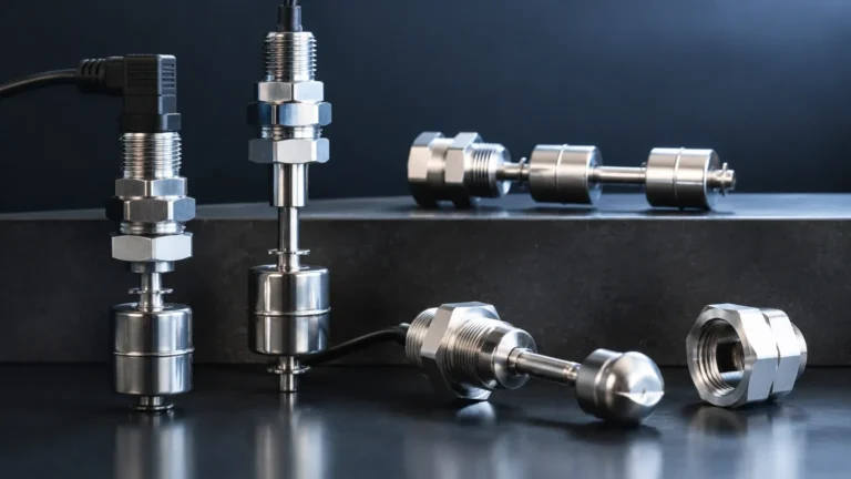
Float switches are the most traditional form of level detection. They operate on Archimedes' principle, where a float—typically made of stainless steel or plastic—rises and falls with the liquid level. Inside the float or the stem, a magnet triggers a reed switch or a microswitch when the float reaches a predetermined height. This mechanical simplicity makes them cost-effective for clean liquids, though they are prone to jamming in viscous or debris-laden fluids.
2. Vibration (Tuning Fork Switches)
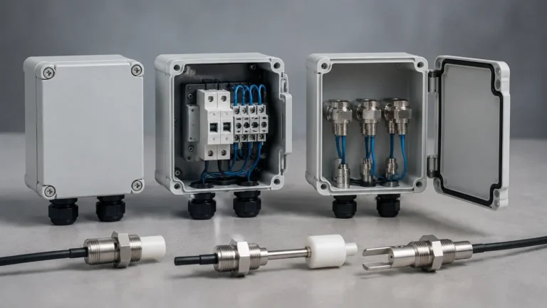
Electronic vibration switches utilize the piezoelectric effect. A sensing element, shaped like a tuning fork, vibrates at its natural resonant frequency in the air. When the fork is submerged in a liquid, the frequency shifts or the amplitude decreases due to the medium's density. An internal circuit detects this change and switches the output relay. These are highly reliable for both liquids and powders and are largely unaffected by foam, turbulence, or bubbles.
3. Capacitance (RF Probes)
Capacitance level switches measure the change in electrical capacitance between the sensor probe and the tank wall (or a reference probe). As the liquid level rises and displaces air, the dielectric constant changes, altering the capacitance. These switches are excellent for detecting interfaces between different liquids or for use in high-temperature and high-pressure environments. However, they require calibration based on the specific dielectric constant of the medium.
4. Conductivity
Conductive level switches are used for electrically conductive liquids like water or acids. A low-voltage current is passed between two electrodes; when the liquid bridges the gap, the circuit is completed. This is a simple, no-moving-parts solution, but it is unsuitable for oils, hydrocarbons, or distilled water which lack conductivity.
Valve Actuation and Control Logic
A level switch valve system is only as effective as its actuation method. Once the level switch detects the threshold, it must communicate with the valve to open or close the flow path. There are three primary types of automated valves used in these systems:
* Solenoid Valves: These use an electromagnetic coil to move a plunger, opening or closing the valve orifice. They are ideal for smaller pipe diameters (typically under 50 mm or 2 inches) and provide rapid response times. They are most commonly used in "on/off" filling applications.
* Motorized (Electric) Ball or Butterfly Valves: For larger pipes or high-viscosity fluids, an electric motor rotates a ball or disc. These valves provide a robust seal and can handle higher pressures than standard solenoids. They are often used in level switch valve setups where a slow, controlled closure is required to prevent water hammer.
* Pneumatic Actuated Valves: In environments where electricity poses a spark risk (ATEX/Ex zones), pneumatic actuators use compressed air to move the valve. The level switch triggers a small pilot solenoid that directs air to the main valve actuator.
Control Logic: High vs. Low Level
* High-Level Cutoff (LSH): The valve is normally open to allow filling. When the level switch detects the liquid, it signals the valve to close, preventing overflow.
* Low-Level Refill (LSL): The valve is normally closed. When the level drops below the switch point, the valve opens to replenish the tank, ensuring a continuous supply for downstream processes.
Practical Selection Table
Choosing the right level switch valve combination requires matching the sensor technology to the fluid properties. The following table provides a general engineering guideline for selection.
| Technology | Media Type | Temp. Range | Pressure Range | Primary Advantage |
| :— | :— | :— | :— | :— |
| Float Switch | Clean Liquids, Water | -40°C to 150°C | Up to 40 bar | Low cost, no power needed (reed type) |
| Tuning Fork | Liquids, Slurries, Powders | -50°C to 250°C | Up to 64 bar | Immune to foam and turbulence |
| Capacitance | Chemicals, Oils, Solids | -100°C to 400°C | Up to 100 bar | Handles extreme temperatures |
| Conductive | Acids, Bases, Tap Water | -20°C to 100°C | Up to 10 bar | No moving parts, very compact |
| Optical | Clear Liquids, Refrigerants | -30°C to 125°C | Up to 50 bar | Extremely small footprint |

Installation and Engineering Considerations
Correct installation is paramount to prevent false triggering and ensure the longevity of the level switch valve assembly. Engineers should adhere to the following best practices:
1. Positioning and Orientation
Level switches can be mounted horizontally (through the side of the tank) or vertically (from the top). For side mounting, ensure the switch is positioned away from the direct path of the inlet flow to avoid mechanical stress or false readings caused by the force of the incoming liquid. If turbulence is expected, a stilling well—a perforated pipe that surrounds the sensor—should be used to dampen surface waves.
2. Wiring and Electrical Safety
When connecting a level switch to a valve, consider the electrical load. Most level switches have small reed relays or transistors that cannot handle the high current required to move a large motorized valve. In these cases, an intermediate power relay or a PLC (Programmable Logic Controller) must be used. Always ensure the voltage of the switch matches the control circuit (e.g., 24V DC or 230V AC).
3. Piping and Valve Sizing
The valve should be sized based on the required flow rate ($m^3/h$) and the allowable pressure drop, rather than just the pipe size. A valve that is too small will restrict flow and increase filling times, while an oversized valve can lead to "hunting," where the system cycles on and off too rapidly.
4. Fail-Safe Configuration
In critical applications, the system must be designed to fail in a safe state. For an overflow prevention system, a "Fail-Closed" valve (normally closed, held open by power) is preferred. If power is lost, the valve automatically shuts, preventing a spill.
Limitations and Maintenance
While level switch valve systems are robust, they are not universal solutions. Certain factors can impede performance:
* Coating and Buildup: In applications involving wastewater or sticky resins, material can build up on the sensor. Tuning forks and capacitance probes are generally better at handling buildup than float switches, but periodic cleaning is still necessary.
* Specific Gravity Changes: Float switches rely on the density of the liquid. If a process switches from a heavy fluid to a light hydrocarbon, the float may no longer be buoyant enough to trigger the switch.
* Mechanical Wear: Any system with moving parts, such as floats or mechanical valve seats, will eventually experience wear. Regular inspection of seals and pivots is recommended every 6 to 12 months depending on the corrosivity of the medium.
Frequently Asked Questions (FAQs)
Q: Can a single level switch control both the start and stop of a pump or valve?
A: Generally, no. A single-point level switch has a very small "deadband" (hysteresis). To prevent the valve from rapidly cycling (chattering) at the setpoint, you typically need two switches: one for the "high" turn-off point and one for the "low" turn-on point.
Q: Is a level switch valve better than a continuous radar level meter?
A: It depends on the goal. For simple automated filling or safety shut-off, a level switch is more reliable and cost-effective. For inventory management or precise process control, a continuous radar meter is superior. Often, both are used together: radar for monitoring and a level switch for redundant high-level protection.
Q: What is the best level switch for thick, viscous oils?
A: Tuning fork switches or high-frequency capacitance probes are usually the best choice for viscous media, as they do not rely on the free movement of a float which could become stuck in the oil.
Q: How do I prevent water hammer when the valve closes?
A: Water hammer occurs when a valve closes too quickly, sending a shockwave through the pipes. To prevent this, use a motorized ball valve with a slower closing time (e.g., 5–10 seconds) or install a surge arrestor in the piping system.
By carefully matching the sensing technology of Welk Level Switches with the appropriate valve actuation, industrial operators can achieve a reliable, automated level control system that minimizes manual intervention and maximizes process safety. For specialized applications involving high pressures or corrosive chemicals, always consult the technical data sheets to ensure material compatibility with the valve body and sensor wetted parts.