Level Switch Parker
Level Switch Parker
In the realm of industrial automation and fluid management, point level detection serves as a critical safeguard for equipment longevity and process efficiency. The term "level switch parker" often refers to high-performance sensing solutions used in hydraulic systems, heavy machinery, and chemical processing. These devices are engineered to provide reliable feedback when a liquid reaches a specific height in a tank or reservoir, preventing dry-running of pumps or overfill conditions that could lead to environmental hazards.
For engineers and procurement specialists, selecting the correct level switch involves understanding the underlying physics of the sensor and how those principles interact with the specific media being measured. As a professional manufacturer, Welk emphasizes that a robust level measurement strategy begins with a technical evaluation of the application environment.
Measurement Principles of Industrial Level Switches
Industrial level switches utilize several distinct physical principles to detect the presence or absence of a liquid. The choice of technology depends heavily on the liquid's properties, such as viscosity, dielectric constant, and transparency.
Optical Level Sensing
Optical level switches are frequently used in applications where compact size and high reliability are paramount. The sensor consists of an infrared LED and a phototransistor. When the sensor tip is in the air, the infrared light is reflected internally within a prism and reaches the receiver. When the tip is submerged in liquid, the light is refracted into the medium, causing the receiver to detect a change in light intensity. This solid-state technology is highly resistant to pressure and temperature fluctuations.
Capacitive Level Sensing
Capacitive switches operate by measuring the change in electrical capacitance between two electrodes (or one electrode and the tank wall). As the liquid level rises and surrounds the probe, the dielectric constant changes, shifting the capacitance. This technology is versatile, capable of detecting both conductive and non-conductive liquids, though it may require calibration for different media.
Magnetic Float Principle
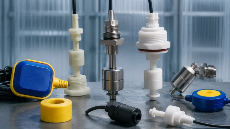
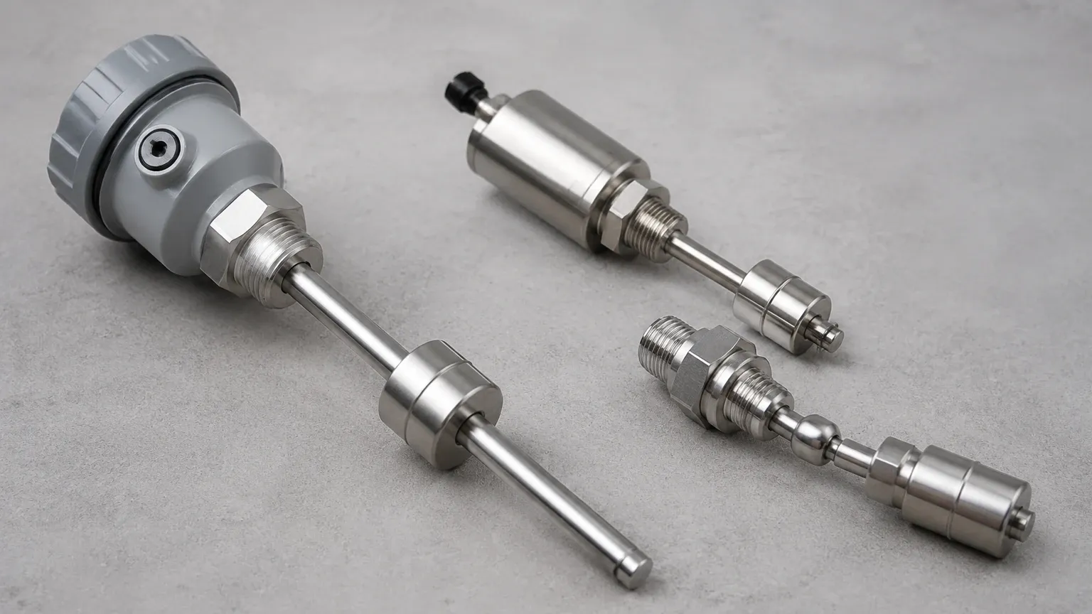
Magnetic float switches are a mechanical solution where a float containing a permanent magnet moves along a stem. Inside the stem, a reed switch is positioned at a specific height. When the float reaches the reed switch, the magnetic field closes (or opens) the circuit. These are valued for their simplicity and the fact that they do not require power to operate the primary sensing element.
Ultrasonic Point Level Detection
Ultrasonic switches use high-frequency sound waves. A transducer emits a pulse that travels through a gap. If the gap is filled with liquid, the sound waves are transmitted efficiently; if the gap is filled with air or gas, the signal is attenuated. This method is effective for a wide range of liquids but can be sensitive to heavy foam or aeration.
Key Evaluation Criteria for Level Switch Selection
When specifying a Level Switches solution, several parameters must be confirmed to ensure long-term reliability. Misalignment between the sensor specification and the process conditions is a primary cause of premature failure.
1. Media Compatibility: The wetted materials (e.g., Stainless Steel 316L, Polysulfone, or PTFE) must be chemically compatible with the fluid. For hydraulic oils, standard polymers often suffice, but aggressive chemicals require specialized fluoropolymers.
2. Operating Pressure: Level switches in hydraulic reservoirs must often withstand significant system pressures. Standard optical switches may be rated up to 50 bar, while specialized high-pressure variants can exceed 100 bar.
3. Temperature Range: Process temperatures can range from cryogenic levels to over 100°C. It is essential to check both the ambient temperature rating for the electronics and the process temperature rating for the sensing element.
4. Output Type: Depending on the control system (PLC or relay logic), the switch may need to provide an NPN/PNP transistor output, a dry contact closure, or a 4-20mA continuous signal (though the latter is typically reserved for level transmitters).
Selection Table for Industrial Applications
The following table provides a general guideline for choosing a level switch technology based on common industrial requirements.
| Application Requirement | Optical Switch | Capacitive Switch | Float Switch | Ultrasonic Switch |
| :— | :— | :— | :— | :— |
| Compact Space | Excellent | Good | Fair | Fair |
| High Viscosity | Poor | Fair | Poor | Good |
| Foaming Liquids | Good | Poor | Good | Poor |
| Coating/Buildup | Fair | Poor | Fair | Good |
| No Moving Parts | Yes | Yes | No | Yes |
| Cost-Efficiency | High | Medium | High | Medium |
Installation Considerations and Best Practices
Proper installation is as vital as the selection of the sensor itself. Even the highest quality level switch can fail if it is positioned incorrectly or exposed to conditions it was not designed to handle.
Orientation and Mounting
Level switches can typically be mounted horizontally (through the side of a tank) or vertically (through the top). Optical and capacitive switches are often preferred for side mounting because they do not have moving parts that could be hindered by gravity or mechanical friction. If using a float switch, ensure the mounting angle allows for the full range of motion of the float.
Turbulence and Sloshing
In tanks with agitators or high-flow return lines, turbulence can cause "chatter"—the rapid opening and closing of the switch. To mitigate this, engineers should use stilling wells or select switches with built-in time delays. Welk recommends a delay of 1 to 5 seconds to filter out momentary level changes caused by splashing.
Electrical Protection
Industrial environments are prone to electrical noise and voltage spikes. Ensure that the level switch is wired with shielded cables and that the power supply is regulated. For inductive loads (like driving a pump motor directly), an external relay or surge suppressor is necessary to protect the internal circuitry of the switch.
Limitations and Common Risks
While level switches are robust, they are not universal solutions. Understanding their limitations prevents system downtime.
* Coating and Scaling: In applications involving wastewater or crystalline chemicals, material can build up on the sensor face. This is particularly problematic for capacitive and optical sensors, as the buildup may simulate the presence of liquid even when the tank is empty.
* Specific Gravity Changes: Float switches rely on buoyancy. If the specific gravity of the liquid changes significantly (e.g., switching from water to a light oil), the float may no longer sit at the correct level or may fail to float entirely.
* Ambient Light Interference: For optical switches, extremely bright, direct sunlight or high-intensity strobe lights can occasionally interfere with the infrared receiver if the sensor housing is not sufficiently shielded.
Frequently Asked Questions (FAQs)
Q: Can a level switch be used for continuous level monitoring?
A: No. A level switch is a "point level" device, meaning it only detects if the liquid is above or below a specific point. For continuous measurement (e.g., 0% to 100% volume), you should use a radar level meter, ultrasonic level sensor, or hydrostatic transmitter.
Q: What is the difference between N.O. and N.C. configurations?
A: N.O. (Normally Open) means the switch circuit is open when the liquid is not present. N.C. (Normally Closed) means the circuit is closed when the liquid is not present. Many modern electronic switches allow the user to select the polarity during installation.
Q: Are these switches suitable for explosive environments?
A: Only if they carry the appropriate certifications, such as ATEX or IECEx. Standard industrial switches are not designed for hazardous areas unless they are used with an intrinsic safety barrier or are housed in explosion-proof enclosures.
Q: How do I clean a fouled level sensor?
A: Most sensors can be cleaned with a soft cloth and a mild solvent compatible with the sensor material. Avoid using abrasive tools on optical prisms or capacitive probes, as scratches can impair performance.
Conclusion
Selecting a level switch for industrial applications requires a balance of technical performance and environmental compatibility. Whether the requirement is for a compact optical sensor for a hydraulic power unit or a robust float switch for a water treatment plant, understanding the measurement principle is the first step toward a reliable installation. By adhering to strict selection criteria and following best practices for installation, operators can ensure that their level detection systems provide accurate, maintenance-free service for years to come.