Level Switch Sump Pump
Level Switch Sump Pump
In industrial and commercial water management, the reliability of a sump pump system is almost entirely dependent on its control mechanism. The level switch serves as the primary sensor that monitors liquid accumulation and triggers the pump to prevent overflow and structural damage. Unlike continuous level transmitters that provide a constant data stream, a level switch is a discrete sensor designed to open or close an electrical circuit at a specific liquid height.
For engineers and facility managers, selecting the correct level switch for a sump pump application requires an understanding of fluid dynamics, electrical ratings, and the physical constraints of the sump pit. This guide explores the technical principles of these switches, selection criteria, and best practices for installation and maintenance in industrial environments.
Measurement Principles of Sump Pump Level Switches
Before selecting a device, it is essential to understand the underlying measurement principles. Level switches for sump pumps generally fall into two categories: mechanical (buoyancy-based) and electronic (solid-state).
1. Mechanical Buoyancy Switches
Mechanical switches rely on a float that moves with the liquid level. As the float reaches a predetermined height, it mechanically activates a switch.
* Tethered Float Switches: These consist of a hollow float containing a microswitch or a metallic ball. The float is attached to a flexible cable. As the water rises, the float pivots upward, causing the ball to roll and activate the switch. These are common in large sumps due to their wide "differential" or "dead band" (the distance between the turn-on and turn-off points).
* Vertical Float Switches: These feature a float that slides up and down a rigid rod. Inside the rod are magnetic reed switches. When the magnet inside the float passes a reed switch, it triggers the pump. These are ideal for narrow sumps where a tethered float might get snagged on the pump or pit walls.
2. Conductive Level Switches
Conductive switches use the liquid itself as part of the electrical circuit. Two or more electrodes are suspended in the sump. When the conductive liquid (such as wastewater or gray water) touches the electrodes, a low-voltage current flows between them, signaling the controller to start the pump. These have no moving parts, making them resistant to mechanical wear, though they are unsuitable for non-conductive liquids like oils.
3. Ultrasonic Level Switches
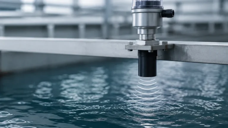
Ultrasonic sensors emit high-frequency sound waves that bounce off the liquid surface. The sensor measures the time of flight to calculate the distance. While often used for continuous measurement, they can be configured as switches to trigger relays at specific heights. This non-contact method is highly effective for corrosive or high-solids liquids that might foul a mechanical float.
4. Diaphragm/Pressure Switches
These switches detect the hydrostatic pressure exerted by the liquid column. As the level rises, the air pressure in a trapped chamber increases, pushing against a diaphragm that activates a microswitch. These are often integrated directly into the pump housing.
Technical Selection Criteria
Choosing a Level Switches solution for a sump pump involves more than just matching a pipe size. Engineers must evaluate the following technical parameters:
Fluid Characteristics
The nature of the liquid is the most significant factor. Clean water applications allow for almost any switch type. However, industrial sumps often contain:
* Suspended Solids: Sewage or industrial runoff can cause mechanical floats to stick or conductive probes to bridge. Non-contact ultrasonic or heavy-duty tethered floats are preferred here.
* Chemical Aggressiveness: If the sump collects chemical waste, the switch material must be compatible. Common materials include Polypropylene (PP), Stainless Steel (316L), and PVC.
* Turbulence: High-inflow sumps can cause floats to bounce, leading to "chatter" (rapid cycling of the pump). In these cases, a switch with a built-in time delay or a vertical float with a stilling well is necessary.
Electrical and Load Requirements
The switch must be rated for the electrical load of the pump motor. Many level switches are designed to carry only signal-level current (e.g., 4-20mA or low-voltage DC) and require an external motor starter or relay. Others are "piggyback" switches that can directly handle the amperage of a 1.5 kW (2 HP) pump. Always verify the voltage (110V, 230V, or 460V) and the maximum current rating (Amps) before installation.
Sump Dimensions and Pump Differential
The "differential" is the distance between the level where the pump starts and where it stops.
* Short Differential: Causes frequent pump cycling, which can overheat the motor and shorten its lifespan.
* Long Differential: Allows the pump to run longer and stay off longer, which is generally better for motor health.
Tethered floats offer the most adjustable differential by changing the length of the cable tether. Vertical floats have a fixed differential based on the placement of the internal reed switches.
Comparison Table: Sump Pump Level Switch Types
| Switch Type | Best Application | Max Temperature | Reliability in Debris | Maintenance Level |
| :— | :— | :— | :— | :— |
| Tethered Float | Large, open pits | 60°C (140°F) | Moderate | Low |
| Vertical Float | Narrow/tight spaces | 90°C (194°F) | Low | Moderate |
| Conductive Probes | Conductive wastewater | 100°C+ | Low (fouling risk) | High |
| Ultrasonic (Point) | Corrosive/Acidic sumps | 80°C (176°F) | High | Very Low |
| Diaphragm | Compact/Submersible | 50°C (122°F) | Moderate | Moderate |
Installation Considerations for Industrial Sumps
Proper installation is as critical as the selection of the switch itself. Failure to follow engineering best practices often leads to premature system failure.
1. Positioning and Clearance
The switch must be positioned so that it does not interfere with the pump, the pit walls, or the inflow pipe. For tethered floats, ensure there is a clear "swing radius." If the float hits a wall, it may get stuck in the "on" position, causing the pump to run dry, or in the "off" position, leading to a flood.
2. The Stilling Well
In sumps with high turbulence or rapid inflow, a stilling well should be used. This is typically a 100 mm to 200 mm (4" to 8") diameter pipe with vent holes that surrounds the level switch. It dampens the surface waves, providing a stable liquid level for the switch to measure, which prevents erratic pump behavior.
3. Cable Management
In industrial environments, cables are susceptible to mechanical damage and chemical degradation. Use cable weights to keep tethered floats in position and ensure that cable entries into junction boxes are sealed with NEMA 4X or IP68 rated glands to prevent moisture ingress.
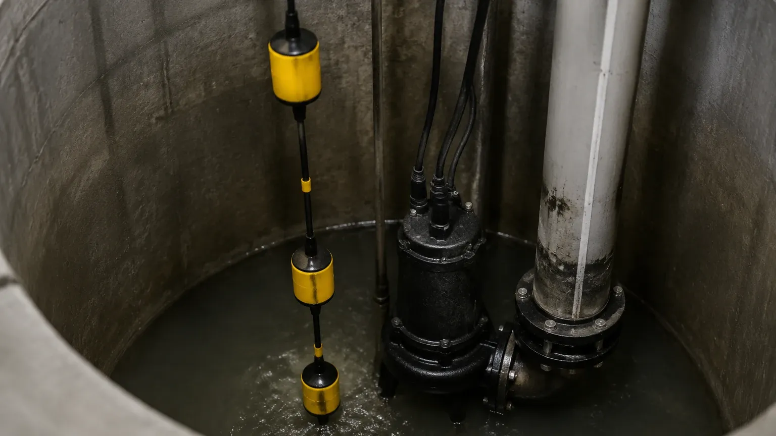
4. Redundancy and Alarms
For critical infrastructure, a single level switch is a single point of failure. Best practice involves a three-switch setup:
1. Low Level (Stop): Shuts off the pump to prevent dry running.
2. High Level (Start): Activates the primary pump.
3. High-High Level (Alarm): Activates a secondary pump or a remote alarm (SCADA/BMS) if the primary system fails.
Common Risks and Limitations
While level switches are robust, they are not infallible. Awareness of these risks can help in designing a more resilient system:
* Mechanical Fatigue: Tethered float cables undergo constant bending. Over several years, the internal copper wiring can fatigue and break. Regular inspection of the cable jacket for cracks is necessary.
* Build-up and Scaling: In hard water or chemical applications, calcium or mineral deposits can build up on floats, making them too heavy to rise. Similarly, grease or oil build-up can coat conductive probes, insulating them from the liquid.
* Air Locking: If a pump starts but the level switch is positioned too high, the pump may draw air, leading to cavitation. Ensure the "stop" level is high enough to keep the pump volute submerged.
* Electrical Interference: For electronic switches (Ultrasonic or Conductive), proximity to high-voltage pump power cables can induce electrical noise. Use shielded cables and maintain physical separation where possible.
Maintenance Checklist
To ensure the longevity of the level switch and the sump pump, implement a semi-annual maintenance schedule:
1. Manual Trigger Test: Manually lift the float or bridge the probes to ensure the pump starts and stops as expected.
2. Debris Removal: Clear any floating debris, grease, or rags from the sump pit that could snag a mechanical switch.
3. Visual Inspection: Check for signs of corrosion on the switch body and check the cable for brittleness or swelling.
4. Continuity Check: Use a multimeter to verify that the switch contacts have low resistance when closed and infinite resistance when open.
Frequently Asked Questions (FAQs)
Q: Can I use a level switch for a sump pump that handles hot condensate?
A: Standard PVC or tethered floats are often rated only up to 50°C or 60°C. For hot condensate (up to 90°C or 100°C), you must use a high-temperature stainless steel vertical float or a specialized conductive probe system.
Q: What is the difference between N.O. and N.C. contacts in a sump application?
A: For a pump-down application (emptying a sump), you typically use a Normally Open (N.O.) switch. When the liquid rises, the switch closes the circuit to start the pump. A Normally Closed (N.C.) switch is used for pump-up applications (filling a tank).
Q: How do I prevent my pump from "short-cycling"?
A: Short-cycling is usually caused by a differential that is too small. If using a tethered float, increase the tether length. If using a vertical float or electronic switch, you may need to move the "start" and "stop" points further apart or implement a lead-lag controller with multiple sensors.
Q: Is a level switch the same as a level transmitter?
A: No. A level switch provides a simple on/off signal at a specific point. A level transmitter provides a continuous signal (like 4-20mA) representing the exact level (e.g., 1.5 meters). Transmitters offer more data but are generally more expensive and require a controller to act as a switch.
By carefully matching the level switch technology to the specific environment of the sump, engineers can significantly reduce the risk of pump failure and flooding. Whether utilizing a simple tethered float for a basic drainage pit or a non-contact ultrasonic sensor for a complex chemical sump, the goal remains the same: reliable, repeatable, and maintenance-free operation.